Mitsubishi Lancer Evolution IX. Manual - part 635
 

  Index      Mitsubishi     Mitsubishi Lancer Evolution IX - service repair manual


Search            


Content   ..  633  634  635  636   ..


Mitsubishi Lancer Evolution IX. Manual - part 635


TROUBLESHOOTING

SUPPLEMENTAL RESTRAINT SYSTEM (SRS)

52B-53

STEP 4. Check a burned-out fuse.
(1) Replace the fuse.
(2) Turn the ignition switch to the "ON" position, wait 

for at least one minute and then turn the ignition 
switch to the "LOCK" (OFF) position. 

(3) Check the fuse.

Q: Is the fuse in good condition?

YES : 

This diagnosis is complete.

NO : 

Go to Step 5.

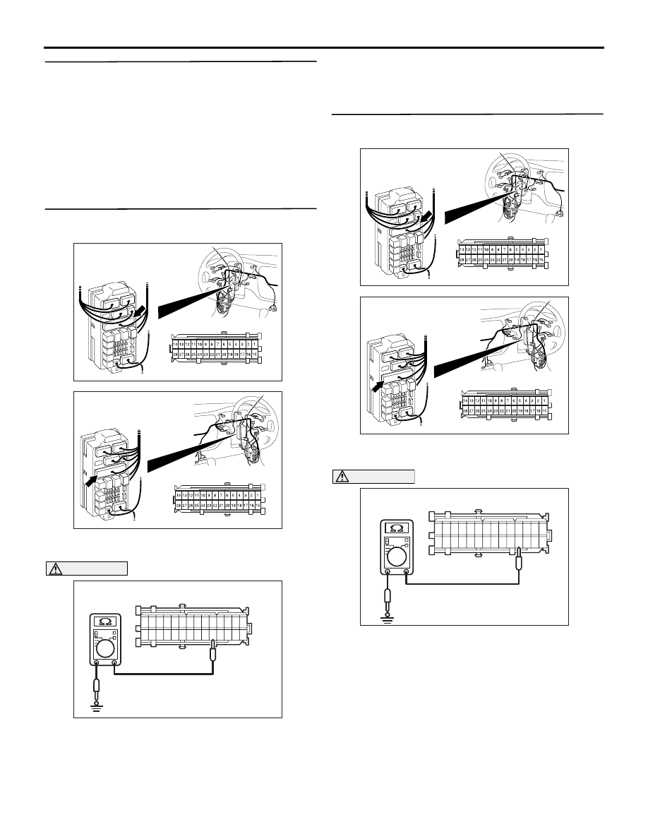
STEP 5. Resistance measurement at the junction 
block connector C-214

(1) Disconnect junction block connector C-214, and 

measure at the wiring harness side.

CAUTION

Do not insert a test probe into the terminal from 
its front side directly as the connector contact 
pressure may be weakened.
(2) Resistance measurement between terminal 24 

and body earth.

OK: Open circuit

Q: Is the check result normal?

YES : 

Go to Step 6.

NO : 

Go to Step 7.

STEP 6. Resistance measurement at junction 
block connector C-214

(1) Disconnect junction block connector C-214, and 

measure at the wiring harness side.

CAUTION

Do not insert a test probe into the terminal from 
its front side directly as the connector contact 
pressure may be weakened.
(2) Resistance measurement between terminal 25 

and body earth.

OK: Open circuit

AC303808

Junction block (front view)

Connector: C-214

AN

<LHD>

Harness side (front view)

AC303822

Junction block (front view)

Connector: C-214

AO

<RHD>

Harness side (front view)

AC106855

1 2 3 4 5 6 7 8 9 10 1112 1314

1516 1718 19 20 212223 242526 2728

C-214 Harness side connector (rear view)

AN

AC303808

Junction block (front view)

Connector: C-214

AN

<LHD>

Harness side (front view)

AC303822

Junction block (front view)

Connector: C-214

AO

<RHD>

Harness side (front view)

Y1729AU

AC106854

1 2 3 4 5 6 7 8 9 10 11 12 13 14

15 16 17 18 19 20 21 22 23 24 25 26 27 28

C-214 Harness side connector (rear view)

AM

TROUBLESHOOTING

SUPPLEMENTAL RESTRAINT SYSTEM (SRS)

52B-54

Q: Is the check result normal?

YES : 

Check the other circuit, which flows through 

fuse number 2.

NO : 

Check the harness wire for short circuit 
between junction block connector C-214 
(terminal No.25) and combination meter 
connector C-01 (terminal No.9), and repair if 
necessary. 

STEP 7. Resistance measurement at the 
SRS-ECU connector C-12

(1) Disconnect SRS-ECU connector C-12, and 

measure at the wiring harness side.

CAUTION

Do not insert a test probe into the terminal from 
its front side directly as the connector contact 
pressure may be weakened.
(2) Resistance measurement between terminal 16 

and body earth.

OK: Open circuit

Q: Is the check result normal?

YES : 

Go to Step 8.

NO : 

Check the harness wire for short circuit 
between SRS-ECU connector C-12 
(terminal No.16) and junction block 
connector C-214 (terminal No.24), and 
repair if necessary. 

STEP 8. Check whether the diagnosis code is 
reset.

Q: Is diagnosis code 41 set?

YES : 

Replace the SRS-ECU (Refer to 

P.52B-109

). 

NO : 

An intermittent malfunction is suspected 
(Refer to GROUP 00 

− How to Use 

Troubleshooting/Inspection Service Points 

P.00-5

). 

AC101950AJ

SRS-ECU

Harness side 
connector 
(rear view)
 

C-12 (Y)

Connector: C-12

AC201665

13 14 15 16 17 18 19 20

5 6 7 8 9 10 11 12

1 2

3 4

AI

C-12 Harness connector 
(rear view)

TROUBLESHOOTING

SUPPLEMENTAL RESTRAINT SYSTEM (SRS)

52B-55

Code No.42: Power supply voltage (IG1 (B) voltage) drops abnormally.

OPERATION

• The SRS-ECU is powered from the ignition 

switch (IG1).

• The SRS-ECU power is supplied from two cir-

cuits. Even if one circuit is shut off, the air bag 
can inflate.

DIAGNOSIS CODE SET CONDITIONS

This diagnosis code is set if the voltage between the 
IG1 terminals (fuse No.3 circuit) and earth is lower 
than a predetermined value for a continuous period 
of 5 second or more. However, if the system returns 
to normal condition, code number 42 will be erased 
automatically and the SRS warning lamp will go out.

PROBABLE CAUSES

• Damaged wiring harnesses or connectors

• Malfunction of the SRS-ECU

IGNITION
SWITCH (IG1)

POWER SOURCE
CIRCUIT

BACK-UP
CAPACITOR

D.C.-D.C.
CONVERTER

MICROCOMPUTER

COMBINATION
METER

WARNING LAMP
DRIVE CIRCUIT

Wire colour code
B : Black     LG : Light green
G : Green     L : Blue
W : White     Y : Yellow
SB : Sky blue     BR : Brown
O : Orange     GR : Gray
R : Red     P : Pink     V : Violet

SRS-ECU

NOTE

: LH drive
  vehicles
: RH drive
  vehicles

IG1 Power Supply Circuit System

TROUBLESHOOTING

SUPPLEMENTAL RESTRAINT SYSTEM (SRS)

52B-56

DIAGNOSIS PROCEDURE

STEP 1. Check junction block fuse number 3.

Q: Is the fuse burned out?

YES : 

Go to Step 4.

NO : 

Go to Step 2.

STEP 2. Voltage measurement at SRS-ECU 
connector C-12
(1) Disconnect the negative battery terminal.

(2) Disconnect SRS-ECU connector C-12.

(3) Connect the negative battery terminal.
(4) Turn the ignition switch to the "ON" position.

CAUTION

Do not insert a test probe into the terminal from 
its front side directly as the connector contact 
pressure may be weakened.
(5) Voltage measurement between C-12 harness 

side connector terminal 13 and body earth.

OK: 9 V or more

Q: Is the check result normal?

YES : 

Go to Step 7.

NO : 

Go to Step 3.

AC301761 AD

Fuse No.3

Junction
block

AC101950AJ

SRS-ECU

Harness side 
connector 
(rear view)
 

C-12 (Y)

Connector: C-12

AC203280

13 14 15 16 17 18 19 20

5 6 7 8 9 10 11 12

1 2

3 4

AH

C-12 Harness side 
connector (rear view)


Content   ..  633  634  635  636   ..