Mitsubishi Lancer Evolution IX. Manual - part 633
 

  Index      Mitsubishi     Mitsubishi Lancer Evolution IX - service repair manual


Search            


Content   ..  631  632  633  634   ..


Mitsubishi Lancer Evolution IX. Manual - part 633


TROUBLESHOOTING

SUPPLEMENTAL RESTRAINT SYSTEM (SRS)

52B-45

DIAGNOSIS PROCEDURE

STEP 1. Check the diagnosis code by connecting 
a dummy resistor. (M.U.T.-II/III diagnosis code)
(1) Disconnect the negative battery terminal.

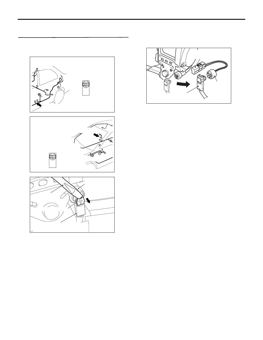
(2) Disconnect passenger's (front) seat belt 

pre-tensioner connector D-03 <LHD> or D-16 
<RHD>. Use a flat-tipped screwdriver to pull out 
the locking button at the harness side connector, 
and then disconnect the connector.

(3) Connect special tool dummy resistor (MB991865) 

to special tool resistor harness (MB991884).

(4) Connect special tool (MB991884) to the D-03 

<LHD> or D-16 <RHD> harness side connector.

(5) Connect the negative battery terminal.
(6) Erase diagnosis code memory, and then check 

the diagnosis code.

Q: Is diagnosis code 29 set?

YES : 

Go to Step 2.

NO : 

Replace the passenger's (front) seat belt 
with pre-tensioner (Refer to 

P.52B-117

). 

AC310465

AO

Connector: D-03
<LHD>

Harness side 
connector 
(front view)

D-03 (B)

AC310471

AJ

Connector: D-16
<RHD>

Harness side 
connector 
(front view)

D-16 (B)

AC300147AX

Flat-tipped 
screwdriver

Locking button

D-03 <LHD>, 
D-16 <RHD> 
Passenger's (front) 
seat belt 
pre-tensioner 
connector

D-03 <LHD>, D-16 <RHD> 
Harness side connector

MB991884
MB991885

AC103283AY

D-03 <LHD>, D-16 <RHD> 
Harness side connector

MB991884
(Resistor
Harness)

MB991865 
(Dummy Resistor : 3  )

TROUBLESHOOTING

SUPPLEMENTAL RESTRAINT SYSTEM (SRS)

52B-46

STEP 2. Resistance measurement between 
SRS-ECU connector C-13 (terminal No.27 and 28) 
and the passenger's (front) seat belt 
pre-tensioner connector D-03 <LHD> or D-16 
<RHD> (terminal No.1 and 2)

(1) Disconnect SRS-ECU connector C-13 and 

passenger's (front) seat belt pre-tensioner 
connector D-03 <LHD> or D-16 <RHD>. For 
connector D-03 <LHD> or D-16 <RHD>, use a 
flat-tipped screwdriver to pull out the locking 
button at the harness side connector, and then 
disconnect the connector.

(2) Connect D-03 <LHD> or D-16 <RHD> harness 

side connector to special tool resistor harness 
(MB991884).

CAUTION

Do not insert a test probe into the terminal from 
its front side directly as the connector contact 
pressure may be weakened.

(3) Resistance measurement between the following 

terminals. 

• SRS-ECU connector C-13 terminal No.27 and 

the special tool terminal No.2

• SRS-ECU connector C-13 terminal No.28 and 

the special tool terminal No.1

OK: Less than 2 

Q: Are the check results normal?

YES : 

Go to Step 3.

NO : 

Repair the harness wires between 
SRS-ECU connector C-13 (terminal No.27 
and 28) passenger’s (front) seat belt 
pre-tensioner connector D-03 <LHD> or 
D-16 <RHD> (terminal No.1 and 2).

AC101951

Connector: C-13

SRS-ECU

AL

C-13 (Y)

21

252627 282930 313233
34 35 3637 38394041 42

22

23 24

Harness side 
connector 
(rear view)
 

AC310465

AO

Connector: D-03
<LHD>

Harness side 
connector 
(front view)

D-03 (B)

AC310471

AJ

Connector: D-16
<RHD>

Harness side 
connector 
(front view)

D-16 (B)

AC300147AX

Flat-tipped 
screwdriver

Locking button

D-03 <LHD>, 
D-16 <RHD> 
Passenger's (front) 
seat belt 
pre-tensioner 
connector

D-03 <LHD>, D-16 <RHD> 
Harness side connector

AC201287BB

MB991884

D-03 <LHD>, 
D-16 <RHD> 
Harness side 
connectors

AC210076

34 35 36 37 38 39 40 41 42

25 26 27 28 29 30 31 32 33

21 22

23 24

2

1

AG

Resister harness 
connector

C-13 Harness side 
connector (rear view)

TROUBLESHOOTING

SUPPLEMENTAL RESTRAINT SYSTEM (SRS)

52B-47

STEP 3.Check whether the diagnosis code is 
reset.

Q: Is diagnosis code 29 set?

YES : 

Replace the SRS-ECU (Refer to 

P.52B-109

).

NO : 

An intermittent malfunction is suspected 
(Refer to GROUP 00 

− How to Use 

Troubleshooting/Inspection Service Points 

P.00-5

). 

Code No.34: SRS-ECU connector lock out of order

DIAGNOSIS CODE SET CONDITIONS

This diagnosis code is set if a poor connection at the 
SRS-ECU is detected. However, if the vehicle condi-
tion returns to normal, diagnosis code number 34 will 
be automatically erased, and the SRS warning lamp 
will go out.

PROBABLE CAUSES

• Damaged connectors

• Malfunction of the SRS-ECU

TROUBLESHOOTING

SUPPLEMENTAL RESTRAINT SYSTEM (SRS)

52B-48

DIAGNOSIS PROCEDURE

STEP 1. Connector lock check: SRS-ECU 
connector C-12 and C-13 (M.U.T.-II/III diagnosis 
code)
(1) Disconnect the negative battery terminal.

(2) Disconnect SRS-ECU connectors C-12 and 

C-13, and then reconnect them.

(3) Connect the negative battery terminal.
(4) Erase diagnosis code memory, and then check 

the diagnosis code.

Q: Is diagnosis code 34 set? 

YES : 

Go to Step 2.

NO : 

The procedure is complete. It is assumed 
that diagnosis code 34 set as connector 
C-12 or C-13 was engaged improperly. 

STEP 2. Connector lock check: SRS-ECU 
connector C-12 and C-13

(1) Disconnect SRS-ECU connectors C-12 and 

C-13. 

(2) Check the connector lock switch terminal inside 

the harness side connector for improper contact 
or deformation.

Q: Are the SRS-ECU connector C-12 and C-13 in good 

condition? 
YES : 

Go to Step 3.

NO : 

Repair the SRS-ECU connector C-12 or 
C-13. 

AC309146

CONNECTORS: C-12, C-13

SRS-ECU

AC

C-13 (Y)

21

252627 282930 313233
34 35 3637 38394041 42

22

23 24

C-13

Harness side
(front view)

C-12 (Y)

C-12

AC006249 AM

SRS-ECU Harness side connector 
(front view)

Connector lock
switch terminal

AC309146

CONNECTORS: C-12, C-13

SRS-ECU

AC

C-13 (Y)

21

252627 282930 313233
34 35 3637 38394041 42

22

23 24

C-13

Harness side
(front view)

C-12 (Y)

C-12

AC006249 AM

SRS-ECU Harness side connector 
(front view)

Connector lock
switch terminal


Content   ..  631  632  633  634   ..