Mitsubishi Lancer Evolution IX. Manual - part 589
 

  Index      Mitsubishi     Mitsubishi Lancer Evolution IX - service repair manual


Search            


Content   ..  587  588  589  590   ..


Mitsubishi Lancer Evolution IX. Manual - part 589


TROUBLESHOOTING <ACD>

MANUAL TRANSMISSION (FF)

22A-39

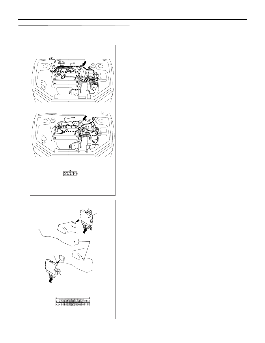
STEP 7. Connectors check: B-03 throttle position 
sensor connector, C-26 4WD-ECU connector, 
C-105 J/C (6).

Check for the contact with terminals.

Q: Is the check result normal?

YES : 

Go to Step 8.

NO : 

Repair the defective connector.

AC311020

Sensor side

B-03 (B)

AC

Connector: B-03

<LH drive vehicles>

<RH drive vehicles>

B-03 (B)

B-03

AC311002

4WD-ECU

Harness side

C-26 (Y)

AC

Connector: C-26

4WD-ECU

C-26 (Y)

Rear console 
assembly

<LH drive vehicles>

<RH drive vehicles>

TROUBLESHOOTING <ACD>

MANUAL TRANSMISSION (FF)

22A-40

STEP 8. Check the harness between throttle 
position sensor connector B-03 terminal No.2 
and 4WD-ECU connector C-26 terminal No.39.

Check the output line for open circuit.

Q: Is the check result normal?

YES : 

Go to Step 5.

NO : 

Repair the wiring harness.

AC311020

Sensor side

B-03 (B)

AC

Connector: B-03

<LH drive vehicles>

<RH drive vehicles>

B-03 (B)

B-03

AC311002

4WD-ECU

Harness side

C-26 (Y)

AC

Connector: C-26

4WD-ECU

C-26 (Y)

Rear console 
assembly

<LH drive vehicles>

<RH drive vehicles>

TROUBLESHOOTING <ACD>

MANUAL TRANSMISSION (FF)

22A-41

Code No.45 Pressure sensor system (open circuit or short circuit)

PRESSURE
SENSOR

4WD-ECU

Pressure sensor system circuit <LH drive vehicles>

Wire colour code
B : Black     LG : Light green
G : Green     L : Blue
W : White     Y : Yellow
SB : Sky blue     BR : Brown
O : Orange     GR : Gray
R : Red     P : Pink     V : Violet

TROUBLESHOOTING <ACD>

MANUAL TRANSMISSION (FF)

22A-42

OPERATION

The 4WD-ECU receives accumulator pressure infor-
mation from the pressure sensor to control the elec-
tric pump.

DIAGNOSIS CODE SET CONDITIONS

Code No.45 is set when the output signal from the 
pressure sensor is below 0.2 V.

PROBABLE CAUSES

• Malfunction of the pressure sensor

• Damaged harness wires and connectors

• Malfunction of the 4WD-ECU

DIAGNOSIS

STEP 1. M.U.T.-II/III data list
Item 18: Pressure sensor (Refer to data list reference 
table 

P.22A-142

).

Q: Is the check result normal?

YES : 

Intermittent malfunction (Refer to GROUP 

00 

− How to Cope with Intermittent 

Malfunction 

P.00-5

).

NO : 

Go to Step 2.

STEP 2. Measure the voltage at 4WD-ECU 
connector C-26.
(1) Turn the ignition switch to the ON position.

PRESSURE
SENSOR

4WD-ECU

Pressure sensor system circuit <RH drive vehicles>

Wire colour code
B : Black     LG : Light green
G : Green     L : Blue
W : White     Y : Yellow
SB : Sky blue     BR : Brown
O : Orange     GR : Gray
R : Red     P : Pink     V : Violet


Content   ..  587  588  589  590   ..