Mitsubishi Lancer Evolution IX. Manual - part 563
 

  Index      Mitsubishi     Mitsubishi Lancer Evolution IX - service repair manual


Search            


Content   ..  561  562  563  564   ..


Mitsubishi Lancer Evolution IX. Manual - part 563


COMPRESSOR ASSEMBLY AND TENSION PULLEY

HEATER, AIR CONDITIONER AND VENTILATION

55-125

REASSEMBLY SERVICE POINTS
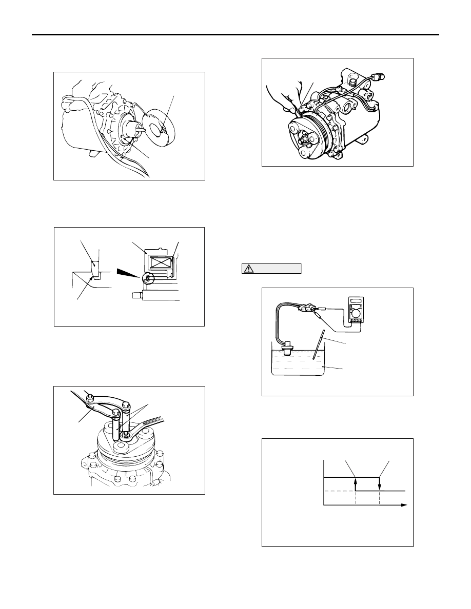
>>A<< FIELD CORE

Line up the pin hole on the compressor unit with the 
field core projection and attach.

>>B<< SNAP RING INSTALLATION

Using snap ring pliers, fit the snap ring so that the 
snap ring’s tapered part is on the outside.

>>C<< SELF-LOCKING NUT 
INSTALLATION

Use the special tools to install the self-locking nut.

• Special spanner (MB991367)

• Pin (MB991386)

>>D<< AIR GAP ADJUSTMENT

Apply voltage from the battery to the magnetic clutch 
and check that the clutch air gap is inside the stand-
ard value. If outside the standard value, use a shim 
to adjust the gap.

Standard value: 0.3 

 0.5 mm

INSPECTION

M1552014301340

REFRIGERANT TEMPERATURE SWITCH

CAUTION

Do not heat more than necessary.

1. Dip the metal part of the cooling temperature 

switch into engine oil and increase the oil 
temperature using a gas burner or similar.

2. When the oil temperature reaches the standard 

value, check that voltage is supplied between the 
terminals.

AC100634 AB

Field core projection

Compressor
unit pin hole

AC001412

Snap ring

Rotor

Clutch coil

Tapered part

AB

AC100633AB

MB991386

MB991367

AC100637AB

Thickness
gauge

AC100787

Thermometer

Engine oil

AB

AC100810

Continuity

No continuity

Oil temperature

AD

120˚C

150˚C

CONDENSER AND CONDENSER FAN MOTOR

HEATER, AIR CONDITIONER AND VENTILATION

55-126

Standard value: 

NOTE: When the oil temperature is 150

°

C or 

more and there is no continuity, the resistance will 
not be 2

 or lower until the oil temperature 

reduces to 120

°

C or less.

CONDENSER AND CONDENSER FAN MOTOR

REMOVAL AND INSTALLATION

M1552006700674

Item

Temperature

Less than 2 
ohms

Slightly below 150

°C

No continuity

150

°C or more

Pre-removal and Post-installation Operation
• Refrigerant Draining and Refilling (Refer to 

P.55-104

).

• Front Bumper Removal and Installation (Refer to GROUP 

51 

P.51-2

).

AC211410

N

2

3

4

1

10

7

9

8

N

10

6

5

AC

12 ± 2 N·m

-Pipe coupling

A/C compressor oil:
  SUN PAG 56

5, 6

N

10

4.9 ± 0.9 N·m

Fan shroud assembly removal 
steps 

<<

A

>>

1.

Fan shroud assembly

2.

Fan

3.

Fan motor

4.

Fan shroud

Condenser removal steps 

<<

B

>>

5.

Flexible discharge hose connection

<<

B

>>

6.

Liquid pipe A connection

>>

A

<<

7.

Condenser

8.

Clamp

9.

Receiver

10. O ring

CONDENSER AND CONDENSER FAN MOTOR

HEATER, AIR CONDITIONER AND VENTILATION

55-127

REMOVAL SERVICE POINT
<<A>> FAN SHROUD ASSEMBLY 
REMOVAL

1. Remove the intercooler mounting bolts/nuts and 

pull the intercooler forward.

2. Move the fan motor/shroud assembly upward for 

removal.

<<B>> FLEXIBLE DISCHARGE 
HOSE/LIQUID PIPE A DISCONNECTION

CAUTION

As the compressor oil and receiver are highly 
moisture absorbent, use a non-porous material 
to plug the hose and nipples.
To prevent the entry of dust or other foreign material, 
plug the dismantled hose and condenser assembly 
nipples. 

INSTALLATION SERVICE POINT
>>A<< CONDENSER INSTALLATION

When replacing the condenser, refill it with a speci-
fied amount of compressor oil and install it to the 
vehicle.

Compressor oil: SUN PAG 56
Quantity: 15 cm

3

 (0.5 floz)

INSPECTION

M1552014301351

CONDENSER FAN MOTOR CHECK

AC211409AC

BATTERY CONNECTION

CONDENSER 
FAN MOTOR 
OPERATION

• Connect connector A-34 

terminal 2 to the positive 
battery terminal

• Connect connector A-35 

terminal 2 to the negative 
battery terminal

Condenser fan 
motor LO 
operation

• Connect connector A-34 

terminal 1 to the positive 
battery terminal

• Connect connector A-35 

terminal 2 to the negative 
battery terminal

Condenser fan 
motor HI 
operation

AC211409

2

1

1 2

AC

A-34

A-35

REFRIGERANT LINE

HEATER, AIR CONDITIONER AND VENTILATION

55-128

REFRIGERANT LINE

REMOVAL AND INSTALLATION <LHD>

M1552006401063

REMOVAL SERVICE POINT
<<A>> HOSE/PIPE DISCONNECTION

CAUTION

As the compressor oil and receiver are highly 
moisture absorbent, use a non-porous material 
to plug the hose and nipples.
To prevent the entry of other foreign bodies, plug the 
condenser, compressor, and expansion valve nip-
ples.

Pre-removal and Post-installation Operation
• Refrigerant Draining and Refilling (Refer to 

P.55-104

).

• Air Cleaner Removal and Installation (Refer to GROUP 

15, Air cleaner 

P.15-5

).

• Radiator Grille Removal and Installation (Refer to 

GROUP 51, Front bumper 

P.51-2

).

AC304553

1

2

3

4

5

6

7

8

N

N

N

N

N

8

8

8

8

High-pressure
side service valve 

Low-pressure side 
service valve 

12 ± 2 N·m

13 ± 1 N·m

4.9 ± 0.9 N·m

25 ± 4 N·m

AE

6

A/C compressor oil: SUN PAG 56

-Pipe coupling

O-ring

O-ring

1, 2, 3,
5, 6

12 ± 2 N·m

Removal steps 

<<

A

>>

1.

Dual pressure switch

<<

A

>>

2.

Liquid pipe A

<<

A

>>

3.

Flexible discharge hose

4.

Expansion valve cover

<<

A

>>

>>

A

<<

5.

Flexible suction hose

<<

A

>>

6.

Liquid pipe B

7.

Expansion valve cover

8.

O-ring


Content   ..  561  562  563  564   ..