Mitsubishi Lancer Evolution IX. Manual - part 561
 

  Index      Mitsubishi     Mitsubishi Lancer Evolution IX - service repair manual


Search            


Content   ..  559  560  561  562   ..


Mitsubishi Lancer Evolution IX. Manual - part 561


SENSORS

HEATER, AIR CONDITIONER AND VENTILATION

55-117

REMOVAL SERVICE POINT
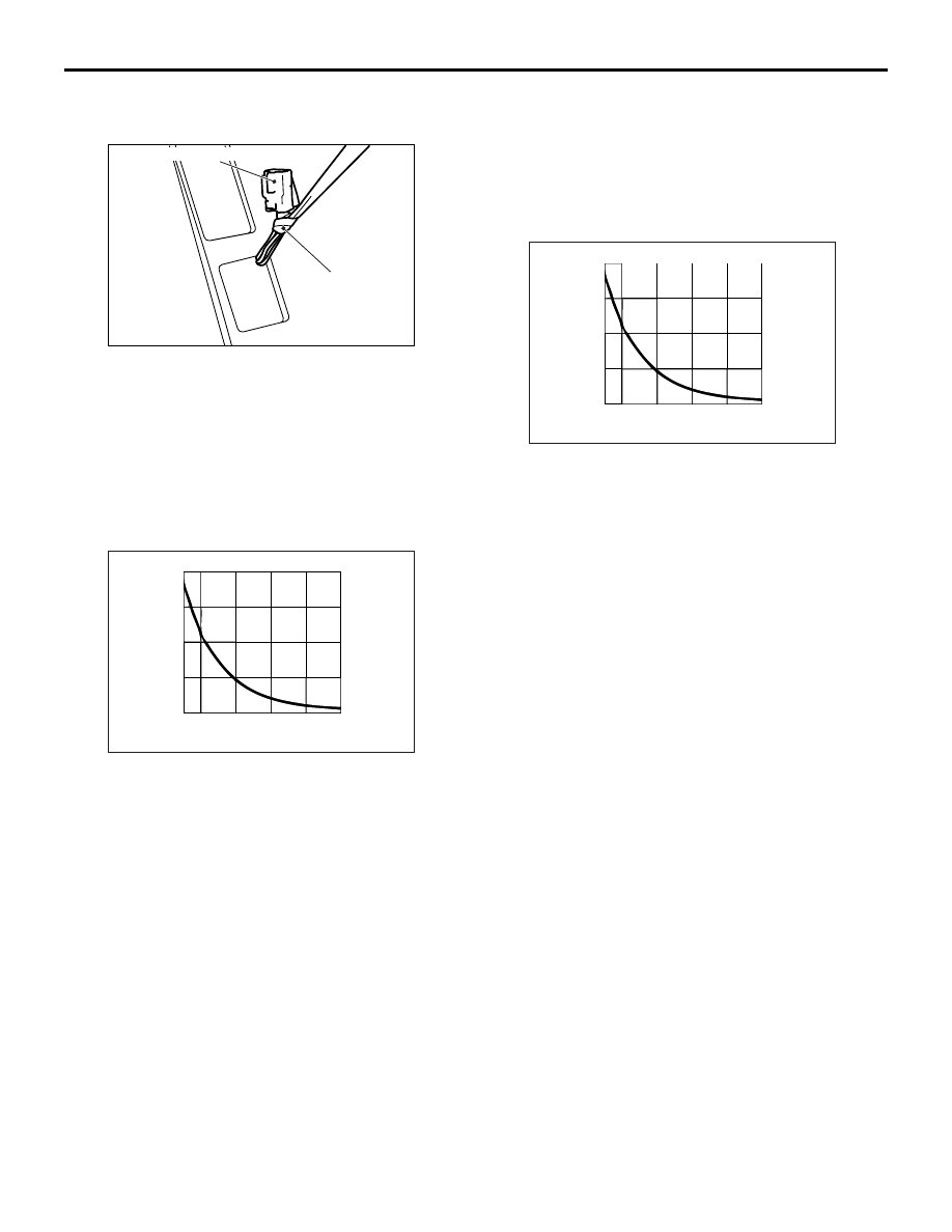
<<A>> PHOTO SENSOR REMOVAL

1. Remove the photo sensor together with the 

defroster nozzle.

2. Suspend the connector with a string to avoid the 

connector drops behind the instrument panel.

INSPECTION

M1552014302150

INTERIOR TEMPERATURE SENSOR 
CHECK

Check to see that the resistance shown in the graph 
is almost satisfied when measuring the resistance 
between the terminals under two or more different 
temperature conditions.

HEATER WATER TEMPERATURE SEN-
SOR CHECK

Check to see that the resistance shown in the graph 
is almost satisfied when measuring the resistance 
between the terminals under two or more different 
temperature conditions.

PHOTO SENSOR CHECK

Check that the blower rotation comes down if the 
photo sensor is covered with hands, when the auto-
matic A/C is operating (in summer sunbeam). If not 
the rotation comes down, replace the photo sensor.

AC504803AB

String

Photo sensor connector

AC503134

20

15

10

5

0

-10 0

20

40

60

80

AB

Resistance
(k )

Temperature (˚C)

AC503134

20

15

10

5

0

-10 0

20

40

60

80

AB

Resistance
(k )

Temperature (˚C)

EVAPORATOR ASSEMBLY

HEATER, AIR CONDITIONER AND VENTILATION

55-118

EVAPORATOR ASSEMBLY

REMOVAL AND INSTALLATION <LHD>

M1552003600496

REMOVAL SERVICE POINT
<<A>> FLEXIBLE SUCTION HOSE/LIQUID 
PIPE B DISCONNECTION

CAUTION

As the compressor oil and receiver are highly 
moisture absorbent, use a non-porous material 
to plug the hose and nipples.
To prevent the entry of dust or other foreign bodies, 
plug the dismantled hose and the nipples of the 
expansion valves.

Pre-removal and Post-installation Operation
• Refrigerant draining and Refilling (Refer to Charging and 

dischargin

P.55-104

).

• Air cleaner and air cleaner air flow sensor assembly 

Removal and Installation (Refer to GROUP 15, Air 

cleaner 

P.15-5

).

AC504937

1, 2, 4, 7

A/C compressor oil:
  SUN PAG 56

O-ring

-Pipe coupling

2

10

1

3

4

7

6

5

9

8

8

12 ± 2 N·m

AB

Removal steps 

<<

A

>>

1.

Flexible suction hose connection

<<

A

>>

2.

Liquid pipe B connection

3.

Expansion valve

4.

Joint 

Glove box (Refer to GROUP 52A, 
Instrument Panel 

P.52A-2

).

Engine-ECU (Refer to GROUP 
13A, Engine-ECU 

P.13A-416

).

5.

Joint duct

Foot duct (RH), Rear heater duct A 
(RH) upper side (Refer to 

P.55-130

).

6.

Evaporator cover

7.

Evaporator

8.

O-ring 

9.

Air thermo sensor clip

10. Air thermo sensor

Removal steps (Continued)

EVAPORATOR ASSEMBLY

HEATER, AIR CONDITIONER AND VENTILATION

55-119

REMOVAL AND INSTALLATION <RHD>

M1552003600504

Pre-removal and Post-installation Operation
• Refrigerant draining and Refilling (Refer to Charging and 

dischargin

P.55-104

).

• Air cleaner and air cleaner air flow sensor assembly 

Removal and Installation (Refer to GROUP 15, Air 

cleaner 

P.15-5

).

AC304886AC

12 ± 2 N·m

7

7

2

1

9

8

6

5

4

3

1, 2, 6

A/C compressor oil:
  SUN PAG 56

O-ring

-Pipe coupling

Removal steps 

<<

A

>>

1.

Flexible suction hose connection

<<

A

>>

2.

Liquid pipe B connection

3.

Expansion valve

Glove box (Refer to GROUP 52A, 
Instrument Panel 

P.52A-2

).

Engine-ECU (Refer to GROUP 
13A, Engine-ECU 

P.13A-416

).

4.

Joint duct

Foot duct (RH), Rear heater duct A 
(RH) upper side (Refer to 

P.55-130

).

5.

Evaporator cover

<<

B

>>

6.

Evaporator

7.

O-ring 

8.

Air thermo sensor clip

9.

Air thermo sensor

Removal steps (Continued)

EVAPORATOR ASSEMBLY

HEATER, AIR CONDITIONER AND VENTILATION

55-120

REMOVAL SERVICE POINT
<<A>> FLEXIBLE SUCTION HOSE/LIQUID 
PIPE B DISCONNECTION

CAUTION

As the compressor oil and receiver are highly 
moisture absorbent, use a non-porous material 
to plug the hose and nipples.
To prevent the entry of dust or other foreign bodies, 
plug the dismantled hose and the nipples of the 
expansion valves.

<<B>> EVAPORATOR REMOVAL

CAUTION

Do not cut the upper side of the pad.

1. When removing the evaporator, cut and fold back 

the dashboard pad as in the diagram (The thick-
ness of the pad interferes with the removal of the 
evaporator). 

2. Remove the evaporator.

INSPECTION

M1552014302161

AIR THERMO SENSOR INSPECTION 

Measure the resistance between connector terminals 
4 and 5 under at least two different temperatures. 
The resistance values should generally match those 
in the graph. 
NOTE: The temperature at the check should not 
exceed the range in the graph. 

AC305312 AB

Dashboard pad

Blower unit

AC103376

Resistance

Temperature (˚C)

-10

0

10

20 30 40

(k )

0

5

10

15

20

25

AB


Content   ..  559  560  561  562   ..