Mitsubishi Lancer Evolution IX. Manual - part 557
 

  Index      Mitsubishi     Mitsubishi Lancer Evolution IX - service repair manual


Search            


Content   ..  555  556  557  558   ..


Mitsubishi Lancer Evolution IX. Manual - part 557


TROUBLESHOOTING

HEATER, AIR CONDITIONER AND VENTILATION

55-101

ACTUATOR TEST TABLE

M1554005200315

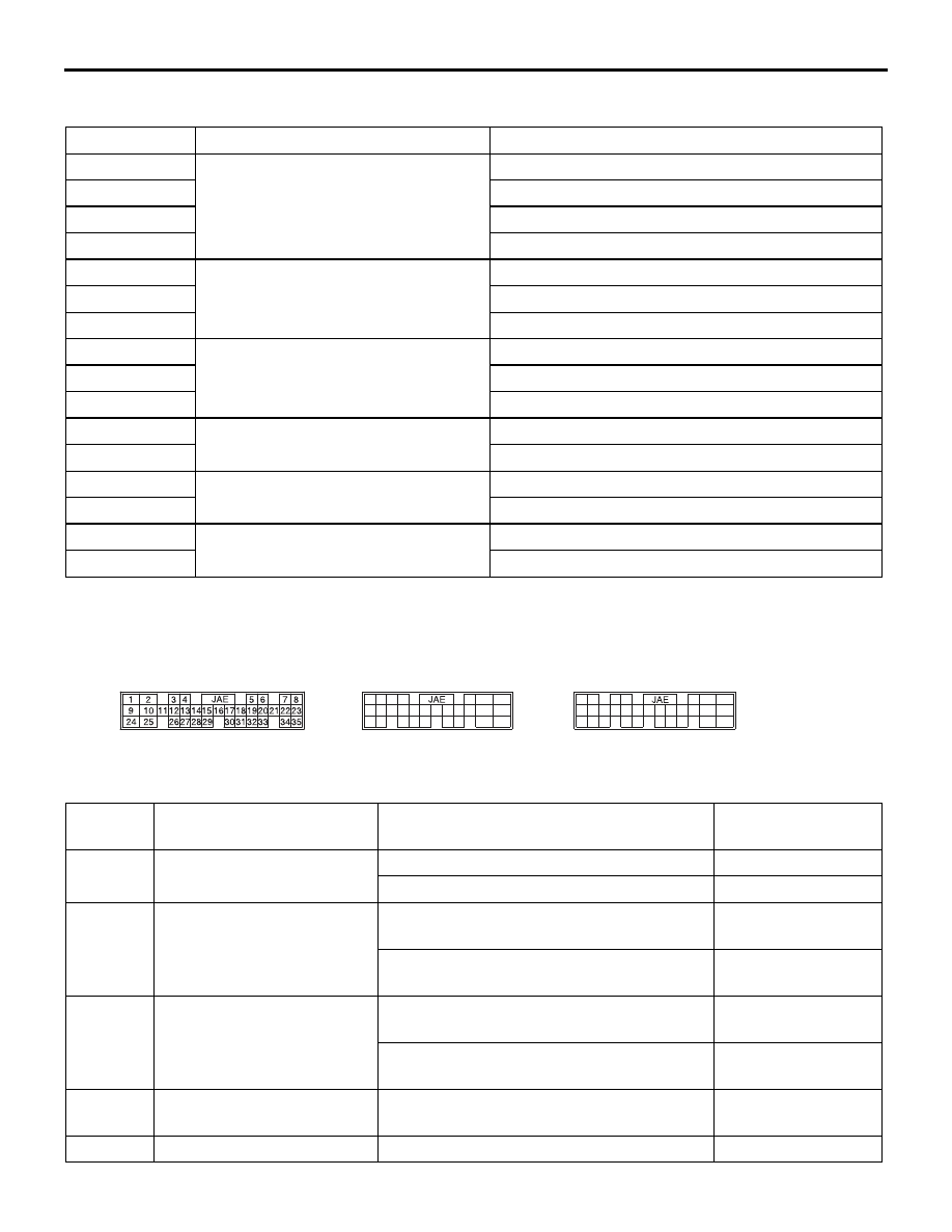
CHECK AT ENGINE-A/T ECU TERMINALS

M1554005400289

Item No.

Check items

Drive content

01

Blower motor

Stop

02

Low speed

03

Middle speed

04

High speed

05

Air mixing damper control motor

Open angle: Approximately 0% (MAX COOL)

06

Opening angle: approximately 50%

07

Open angle: Approximately 100% (MAX HOT)

08

Mode selection damper control motor FACE

09

FOOT

10

DEF

11

Compressor output

OFF

12

ON

13

Outside/inside air selection damper 
control motor

Outside air

14

Inside air

38

Idle-up

OFF (A/C high pressure)

39

ON (A/C low pressure)

45

43

42

41

44

52

61

60

4849

63

51
62

50

66

55
65

54

64

53

5657

47

46

67

58

68

59

95

83

94

93

92

91

80

79

72

71
78

82

73

81

74

98

97

96

86

85

84

87

75

88

100

99

76

89

77

90

AC504605

<C-121>

<C-119>

<C-117>

AB

Terminal 
No.

Check items

Check conditions

Normal conditions

20

Output to A/C compressor

A/C compressor relay: OFF

System voltage

A/C compressor relay: ON

0 V

30

Condenser fan motor relay 
(HI)

Fan inactive state (Engine coolant 
temperature: 90

°C or less

System voltage

Fan high-speed rotation state (Engine 
coolant temperature: 105

°C or less

1 V or less

31

Condenser fan motor relay 
(LOW)

Fan inactive state (Engine coolant 
temperature: 90

°C or less)

System voltage

Fan low-speed rotation state (Engine 
coolant temperature: 95 

− 100°C or less)

1 V or less

83

Input from A/C-ECU (A/C1) When the A/C is in operation (When the air 

thermo sensor detects 3

°C or more).

System voltage

65

Input from A/C-ECU (A/C2) When the A/C is under low load

System voltage

TROUBLESHOOTING

HEATER, AIR CONDITIONER AND VENTILATION

55-102

CHECK AT A/C-ECU TERMINALS

M1554005400290

8

2

1

5

3 4

6 7

9 10

20

19

18

17

16

15

14

13

12

11

32

24

29

21

31

30

2223

27

35

33

25

34

26

36

28

AC300196

<C-36>

<C-37>

AC

Terminal 
No.

Check items

Check conditions

Normal conditions

1

Interior temperature sensor

Sensor temperature: 25

°C (4kΩ)

2.1

− 2.7V

2

Output to blower pulse controller

When the blower is operating.

− 2.5V (Effective 

alternating voltage)

3

Back-up power supply

Always

System voltage

4

Input from heater water temperature 
sensor

Sensor temperature: 25

°C (4kΩ)

2.1 

− 2.7V

5

Input from air mixing damper control 
motor potentiometer

When the damper flaps is moving to 
the MAX HOT position.

4.1 

− 4.6 V

6

Input from mode selection damper 
control motor potentiometer

When the damper is moved to the 
DEF position.

4.1 

− 4.6 V

7

Input from the outside thermo sensor Sensor temperature: 25

°C (4kΩ)

2.1 

− 2.7 V

8

Input from the air thermo sensor

Sensor temperature: 25

°C (4kΩ)

2.1 

− 2.7 V

9

Photo sensor (-)

Brightness is 0 lux

4.9 

− 5.1 V

Brightness is 100,000 lux or more 

Approximately 0 V 

10

Potentiometer power supply

Always

5 V

11

Input from the A/C pressure sensor

2.6 MPa

3.9 V

12 

− 15 -

-

-

16

Rear defogger

When the rear defogger is operating.  2.0 V or less
When the rear defogger is stopped

System voltage

17

Diagnosis set

Ignition switch: ON

A voltmeter needle 
fluctuates between 
0 and 12 V.

18

Input from diagnosis

Ignition switch: ON

Approximately 5 V 

19

Photo sensor (+)

Always

0 V

20

Sensors and potentiometers earth

Always

0 V

21

Air outlet changeover damper motor 
(FACE)

When the damper is moved to the 
FACE position.

10 V

When the damper is moved to the 
DEF position.

Faint voltage (0.5 
V) 

22

Air mix damper motor (MAX COOL)

When the damper flaps is moving to 
the MAX COOL position.

10 V

When the damper flaps is moving to 
the MAX HOT position.

Faint voltage (0.5 
V) 

TROUBLESHOOTING

HEATER, AIR CONDITIONER AND VENTILATION

55-103

23

Outside/inside air selection damper 
control motor (outside)

When the damper is moved to the 
inside air recirculation position

10 V (When the 
motor is stopped)

When the damper is moved to the 
outside air inside air intake position

2.0 V or less

24

Mode selection damper control motor 
and potentiometer (DEF)

When the damper is moved to the 
FACE position.

Faint voltage (0.5 
V) 

When the damper is moved to the 
DEF position.

10 V

25

Air mixing damper control motor and 
potentiometer (MAX HOT)

When the damper flaps is moving to 
the MAX COOL position.

Faint voltage (0.5 
V) 

When the damper flaps is moving to 
the MAX HOT position.

10 V

26

outside/inside air selection damper 
control motor (inside)

When the damper is moved to the 
inside air recirculation position

2.0 V or less

When the damper is moved to the 
outside air inside air intake position

10 V (When the 
motor is stopped)

27

Earth

Always

Continuity exists.

28

IG2 power supply

Ignition switch: ON

System voltage

29

Illumination earth

Always

Continuity exists.

30

ILL power supply

Lighting switch: ON

System voltage

31

-

-

-

32

Input from the engine-A/T-ECU 
(A/C2)

When the A/C is under low load

System voltage

33

Input from the compressor relay

Compressor: ON

System voltage

34

Input from the engine-A/T-ECU 
(A/C1)

When the A/C is stopped

0 V

When the A/C is operating (When the 
compressor is operating)

System voltage

35

-

-

-

36

ACC power supply

Ignition switch: ACC

System voltage

Terminal 
No.

Check items

Check conditions

Normal conditions

ON-VEHICLE SERVICE

HEATER, AIR CONDITIONER AND VENTILATION

55-104

ON-VEHICLE SERVICE

MAGNETIC CLUTCH TEST

M1552008500483

1. Disconnect the magnetic clutch connector to the 

magnetic clutch.

2. Connect positive battery voltage directly to the 

connector for the magnetic clutch.

3. If the magnetic clutch is normal, there will be a 

"click." If the pulley and armature do not make 
contact ("click"), there is a malfunction.

COMPRESSOR DRIVE BELT 
ADJUSTMENT

M1552001000409

Refer to GROUP 11A, On-vehicle Service 

− Drive 

Belt Tension Check 

P.11A-7

.

DUAL PRESSURE SWITCH CHECK

M1552010400375

1. Remove the dual pressure switch connector and 

connect the high/low pressure side terminals 
located on the harness side as shown in the 
illustration.

2. Install a gauge manifold to the high-pressure side 

service valve of the refrigerant line (Refer to 

P.55-128

P.55-129

).

3. When the high/low pressure sides of the dual 

pressure switch are at operation pressure (ON) 
the resistance should less than two ohms 
between the terminals. If open circuit, replace the 
switch.

CHARGING AND DISCHARGING

M1552022200044

Use the refrigerant recovery unit to discharge refrig-
erant gas front the system.
NOTE: Refer to the Refrigerant Recovery and Recy-
cling Unit instruction Manual for operation of the unit.

REFILLING OF OIL IN THE A/C SYSTEM

M1552020000066

Too little oil will provide inadequate compressor lubri-
cation and cause a compressor failure. Too much oil 
will increase discharge air temperature.
When a compressor is installed at the factory, it con-
tains 120 mL of compressor oil. While the A/C sys-
tem is in operation, the oil is carried through the 
entire system by the refrigerant. Some of this oil will 
be trapped and retained in various parts of the sys-
tem.
When the following system components are 
changed, it is necessary to add oil to the system to 
replace the oil being removed with the component.

Compressor oil: SUN PAG 56
Quantity

Evaporator: 60 mL
Condenser: 15 mL
Flexible suction hose: 10 mL
Receiver: 10 mL

PERFORMANCE TEST 

M1552001400429

1. The vehicles to be tested should be in a place that 

is not in direct sunlight.

AC005671

Magnetic clutch connector

AC

AC001368 AD

High/Low
Pressure Side

Low-pressure side

High-pressure side

ON

OFF

ON

OFF

2650 ± 200

2060 ± 200

230 ± 20

210 ± 25

(kPa)


Content   ..  555  556  557  558   ..