Mitsubishi Lancer Evolution IX. Manual - part 556
 

  Index      Mitsubishi     Mitsubishi Lancer Evolution IX - service repair manual


Search            


Content   ..  554  555  556  557   ..


Mitsubishi Lancer Evolution IX. Manual - part 556


TROUBLESHOOTING

HEATER, AIR CONDITIONER AND VENTILATION

55-97

STEP 18. Check the wiring harness between 
A-06X condenser fan relay (LO) connector 
terminal No.3 and C-121 engine-ECU connector 
terminal No.31.

NOTE: 

Prior to the wiring harness inspection, check interme-
diate connector A-29 <LHD> or C-31 <RHD>, and 
repair if necessary.

• Check the condenser fan relay (HI) earth line for 

open or short circuit.

Q: Is the check result normal?

YES : 

 Go to Step 19.

NO : 

Repair the wiring harness.

AC311017AC

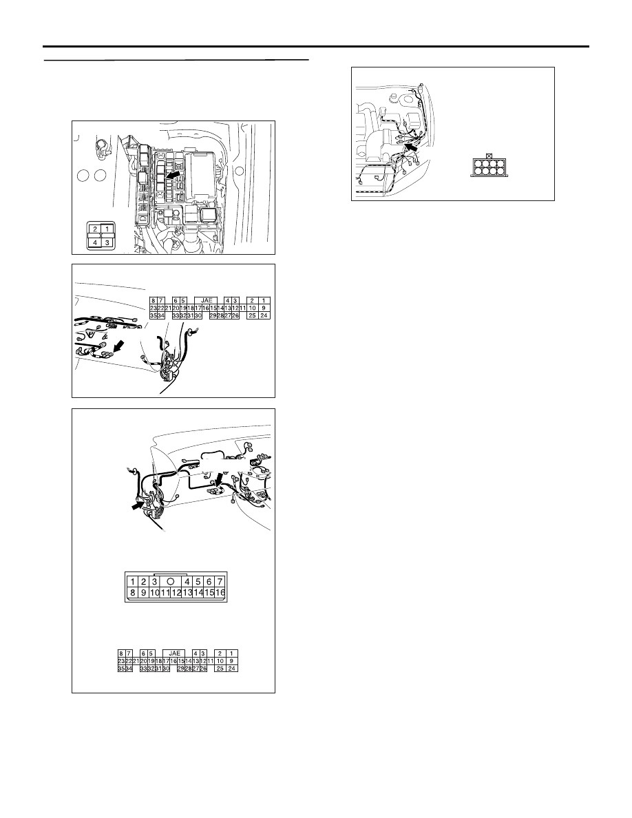
Connector: A-06X

Relay box side

AC504617AB

Connector: C-121 <LHD>

C-121 (GR)

Harness side

AC504624AT

Connectors: C-31, C-121 <RHD>

C-121

Harness side

C-121 (GR)

C-31

C-31

AC310542

6

2

5

1

8

7

3 4

Connector: A-29 <LHD>

AB

A-29 (B)

TROUBLESHOOTING

HEATER, AIR CONDITIONER AND VENTILATION

55-98

STEP 19. Check the wiring harness between 
A-06X condenser fan relay (LO) connector 
terminal No.1 and A-34 condenser fan motor 
connector terminal No.2.

• Check the condenser fan motor power supply line 

for open circuit.

Q: Is the check result normal?

YES : 

The trouble can be an intermittent 

malfunction (Refer to GROUP 00, How to 
Cope with Intermittent Malfunction 

P.00-5

).

NO : 

Repair the wiring harness.

STEP 20. Connector check: A-35 condenser fan 
motor connector

Q:  Is the check result normal?

YES : 

Go to Step 21.

NO : 

Repair the connector.

AC311017AC

Connector: A-06X

Relay box side

AC310431

Harness side

Connector: A-34 <LHD>

AG

A-34 (B)

AC310433

Harness side

Connector: A-34 <RHD>

AF

A-34 (B)

AC310431

A-35 (GR)

Connector: A-35 <LHD>

Harness side

AH

AC310433

A-35 (GR)

Connector: A-35 <RHD>

Harness side

AG

TROUBLESHOOTING

HEATER, AIR CONDITIONER AND VENTILATION

55-99

STEP 21. Resistance measurement at A-35 
condenser fan motor connector.

(1) Disconnect the connector, and measure at the 

wiring harness side.

(2) Measure the resistance value between terminal 1 

and earth.

OK: 2 ohms or less

Q: Is the check result normal?

YES : 

Replace the engine-ECU.

NO : 

 Go to Step 22.

STEP 22. Check the wiring harness between A-35 
condenser fan motor connector terminal No.1 
and earth.

• Check the condenser fan motor earth line for 

open circuit.

Q: Is the check result normal?

YES : 

The trouble can be an intermittent 

malfunction (Refer to GROUP 00, How to 
Cope with Intermittent Malfunction 

P.00-5

).

NO : 

Repair the wiring harness.

AC310431

A-35 (GR)

Connector: A-35 <LHD>

Harness side

AH

AC310433

A-35 (GR)

Connector: A-35 <RHD>

Harness side

AG

AC310506

AC310506AO

Connector: A-35 
(Harness side)

AC310431

A-35 (GR)

Connector: A-35 <LHD>

Harness side

AH

AC310433

A-35 (GR)

Connector: A-35 <RHD>

Harness side

AG

TROUBLESHOOTING

HEATER, AIR CONDITIONER AND VENTILATION

55-100

DATA LIST REFERENCE TABLE

M1554005100341

Item No.

Check items

Inspection conditions

Normal condition

11

Interior temperature sensor Turn the ignition switch to 

the ON position.

Room temperature is the 
same as M.U.T.-II/III 
displayed temperature.

13

Outside thermo sensor

Turn the ignition switch to 
the ON position.

Outside temperature is the 
same as M.U.T.-II/III 
displayed temperature.

15

Heater water temperature 
sensor

Turn the ignition switch to 
the ON position.

Heater core wall surface 
temperature is the same as 
M.U.T.-II/III displayed 
temperature.

21

Air thermo sensor

Turn the ignition switch to 
the ON position.

Evaporator outlet temperate 
is the same as M.U.T.-II/III 
displayed temperature

25

Photo sensor

• Turn the ignition switch to 

the ON position.

• Change the volume of 

insolation.

The volume of insolation 
takes inverse proportion with 
the M.U.T.-II/III displayed 
voltage.

31

Air mixing damper control 
motor and potentiometer

• Turn the ignition switch to 

the ON position.

• Door position: MAX HOT

Opening angle: approximately 
100%

• Turn the ignition switch to 

the ON position.

• Door position: MAX 

COOL

Opening angle: approximately 
0%

32

Mode selection damper 
control motor and 
potentiometer

• Turn the ignition switch to 

the ON position.

• Damper position: FACE

Opening angle: approximately 
0%

• Turn the ignition switch to 

the ON position.

• Damper position: FOOT

Opening angle: approximately 
60%

• Turn the ignition switch to 

the ON position.

• Damper position: 

FOOT/DEF

Opening angle: approximately 
80%

• Turn the ignition switch to 

the ON position.

• Damper position: DEF

Opening angle: approximately 
100%

42

A/C pressure sensor

Turn the ignition switch to 
the ON position.

A/C refrigerant pressure is the 
same as M.U.T.-II/III 
displayed pressure.


Content   ..  554  555  556  557   ..