Mitsubishi Lancer Evolution IX. Manual - part 527
 

  Index      Mitsubishi     Mitsubishi Lancer Evolution IX - service repair manual


Search            


Content   ..  525  526  527  528   ..


Mitsubishi Lancer Evolution IX. Manual - part 527


ON-VEHICLE SERVICE

ANTI-SKID BRAKING SYSTEM (ABS)

35B-139

3. Manually turn the wheel to be measured 1/2 to 1 

turn/second. Measure the output voltage with a 
voltmeter or oscilloscope.
NOTE: The output waveform is low when the 
wheel speed is low. Similarly, it will be higher as 
the wheel speed increases. Waveform may also 
be observed by driving the vehicle.

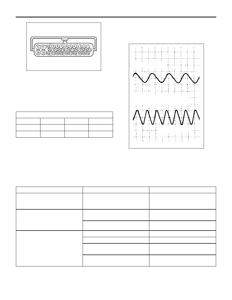
Output voltage:

• Minimal voltmeter reading: 42 mV

• Maximum voltmeter reading: 300 mV

• Minimal oscilloscope reading: 120 mV

• Maximum oscilloscope reading: 600 mV

Probable causes of low output voltage

• Wheel speed sensor pole piece-to-wheel speed 

rotor clearance too large

• Faulty wheel speed sensor

NOTE: Check the connection of the wheel speed 
sensor harness and connector before using the 
oscilloscope.

4. To observe the waveform with an oscilloscope:

• Front Wheels: Shift into low gear and drive the 

wheels.

• Rear Wheels: Turn the wheels manually at a con-

stant speed.

POINTS IN WAVEFORM MEASUREMENT

NOTE: The wheel speed sensor cable moves in relation to motion of the front or rear suspension. Therefore, 
it is likely that it has an open circuit only when driving on rough roads but it functions normally when driving on 
smooth roads. It is recommended to observe sensor output voltage waveform also under special conditions, 
such as driving on a rough road.

Terminal No.
Front left

Front right

Rear left

Rear right

22

29

6

8

31

30

7

9

AC211695AB

AC000949 AF

When turned by hand

When idling (5 − 6 km/h), with 1st gear

[10.0 ms/DIV IV/DIV]

Symptom

Probable causes

Remedy

Too small or zero waveform 
amplitude

Faulty wheel speed sensor or 
excessive gap between it and the 
wheel speed rotor

Replace wheel speed sensor

Waveform amplitude fluctuates 
excessively (This is no problem if 
the minimum amplitude is 100 mV 
or more)

Axle hub eccentric or with large 
runout

Replace hub assembly

Faulty ABS-ECU earth

Repair harness wires

Noisy or disturbed waveform

Open circuit in wheel speed sensor Replace wheel speed sensor
Open circuit in harness

Repair harness wire

Incorrectly mounted wheel speed 
sensor

Mount wheel speed sensor 
correctly

Wheel speed rotor with missing or 
damaged teeth

Replace wheel speed rotor

ON-VEHICLE SERVICE

ANTI-SKID BRAKING SYSTEM (ABS)

35B-140

HYDRAULIC UNIT CHECK

M1352001700642

CAUTION

• The roller of the braking force tester and the 

tyre should be dry during testing.

• When testing the front brakes, apply the park-

ing brake. When testing the rear brakes, stop 
the front wheels with chocks.

1. Jack up the vehicle. Then support the vehicle with 

rigid racks at the specified jack-up points or place 
the front or rear wheels on the rollers of the 
braking force tester.

2. Release the parking brake, and feel the drag force 

(drag torque) on each road wheel. When using 
the braking force tester, take a reading of the 
brake drag force.

3.  Turn the ignition switch to the "LOCK" (OFF) 

position.

CAUTION

To prevent damage to the M.U.T.-II/III, always turn 
the ignition switch to the "LOOK" (OFF) position 
before connecting or disconnecting the 
M.U.T.-II/III.

4.  Connect the M.U.T.-II/III as shown in the 

illustration.

5. After checking that the shift lever is in neutral, 

start the engine.

6. Use the M.U.T.-II/III to force-drive the actuator. 

For the M.U.T.-II/III, follow the steps below.
(1) Select "Interactive Diagnosis" from the start-up 

screen.

(2) Select "System select."
(3) Choose "ABS" from the "CHASSIS" tab.
(4) Select "Actuator Test" from "ABS" screen

AC207179AB

M.U.T.-II

16-PIN

<Using the M.U.T.-II>

AC210056

AC

MB991911

16-PIN

MB991827

MB991824 

<Using the M.U.T.-III>

ON-VEHICLE SERVICE

ANTI-SKID BRAKING SYSTEM (ABS)

35B-141

(5) Choose an appropriate item for hydraulic unit 

check.

NOTE: The ABS system will switch to the 
M.U.T.-II/III mode and the ABS warning lamp 
will illuminate.

NOTE: When the ABS has been interrupted by 
the fail-safe function, the M.U.T.-II/III actuator 
testing cannot be used.

7. Turn the wheel by hand and check the change in 

braking force when the brake pedal is depressed. 
When using the braking force tester, depress the 
brake pedal until the braking force is at the 
following values, and check that the braking force 
changes to the reading taken in step 2. The result 
should be as shown in the diagram above.

AC000954AH

M.U.T.-II/III actuator test
(Item No.01, 02, 03, 04) start

1 seconds

2 seconds

3 seconds

Depressed

Released

Increase in pressure

Reduction in pressure

Steady pressure

Lock

Drag force when the
pedal is free

Pedal
operation

Solenoid
valve
position

Checking
the brake
force

Approx. 0.05 second

Front wheel

785 

− 981 N

Rear wheel

588 

− 784 N

ON-VEHICLE SERVICE

ANTI-SKID BRAKING SYSTEM (ABS)

35B-142

8. If the result of inspection is abnormal, repair 

according to the Diagnosis Table below.

9. After inspection, disconnect the M.U.T.-II/III 

immediately after turning the ignition switch to the 
"LOCK" (OFF) position. 

IN THE EVENT OF A DISCHARGED 
BATTERY

M1352003500600

WARNING

If the ABS is not operating, the vehicle pos-
ture will be unstable during braking, Do not 
drive the vehicle with the ABS-ECU connec-
tor disconnected or with the ABS not operat-
ing for any other reason.

If the engine is started using a booster cable when 
the battery is completely flat, and the vehicle is then 
driven without waiting for the battery to be recharged, 
the engine may misfire and it may not be possible to 
drive the vehicle. This is because the ABS consumes 
a large amount of current when carrying out its initial 
checks. If this happens, recharge the battery fully.

Diagnosis Table

M.U.T.-II/III Display Operation

Inspection result

Judgment Probable cause

Remedy

01 FR VALVE
02 FL VALVE
03 RR VALVE
04 RL VALVE

• Depress brake pedal 

to lock wheel.

• Using the M.U.T.-II/III, 

select the wheel to be 
checked and force the 
actuator to operate.

• Turn the selected 

wheel manually to 
check the change of 
brake force.

Brake force is 
released for 
three seconds 
after wheels 
have been 
locked.

Normal −

Wheel does not 
lock when brake 
pedal is 
depressed.

Abnorm
al

Clogged brake 
line other than 
hydraulic unit

Check and clean 
brake line

Clogged 
hydraulic circuit 
in hydraulic unit

Replace 
hydraulic unit 
assembly

Brake force is 
not released

Incorrect 
hydraulic unit 
brake tube 
connection

Connect correctly

Hydraulic unit 
solenoid valve 
not functioning 
correctly

Replace 
hydraulic unit 
assembly


Content   ..  525  526  527  528   ..