Mitsubishi Lancer Evolution IX. Manual - part 482
 

  Index      Mitsubishi     Mitsubishi Lancer Evolution IX - service repair manual


Search            


Content   ..  480  481  482  483   ..


Mitsubishi Lancer Evolution IX. Manual - part 482


ON-VEHICLE SERVICE

MULTIPORT FUEL INJECTION (MPI)

13A-403

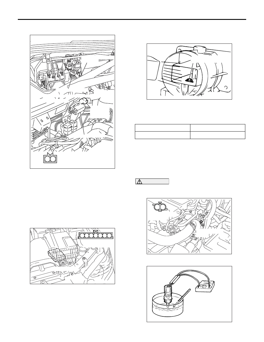
FUEL PUMP RESISTOR CHECK

M1131052700049

1. Disconnect the fuel pump resistor connector.
2. Measure the resistance between terminals.

Standard value: 0.45 

 0.65 

3. If the resistance is out of specification, replace the 

fuel pump resistor.

INTAKE AIR TEMPERATURE SENSOR 
CHECK

M1131002801118

1. Disconnect the air flow sensor connector.
2. Measure resistance between terminals No. 5 and 

No. 6.

Standard value:

13 

 17 k (at 20°C)

5.3 

 6.7 k (at 0°C)

2.3 

 3.0 k (at 20°C)

1.0 

 1.5 k (at 40°C)

0.56 

 0.76 k (at 60°C)

0.30 

 0.42 k (at 80°C)

3. Measure resistance while heating the sensor 

using a hair drier.

Normal condition:

4. If the value deviates from the standard value or 

the resistance remains unchanged, replace the air 
flow sensor assembly.

ENGINE COOLANT TEMPERATURE 
SENSOR CHECK

M1131003101060

CAUTION

Be careful not to touch the connector (resin sec-
tion) with the tool when removing and installing.

1. Remove the engine coolant temperature sensor.

AK304577

1 2

AB

Fuel pump resistor

Equipment side connector

<L. H. drive vehicles>

<R. H. drive vehicles>

Fuel pump resistor
connector

Fuel pump resistor

Fuel pump 
resistor
connector

AK304578

6 7

1 2 3 4 5

AB

Air flow sensor

Equipment side 
connector

Temperature (

°C)

Resistance (k

)

Higher

Smaller

AKX01621

Intake air temperature
sensor

AD

AK304579

1 2

AB

Equipment side 
connector

Engine coolant
sensor

AKX01622

ON-VEHICLE SERVICE

MULTIPORT FUEL INJECTION (MPI)

13A-404

2. With temperature sensing portion of engine 

coolant temperature sensor immersed in hot 
water, check resistance.

Standard value:

14 

 17 k (at 20°C)

5.1 

 6.5 k (at 0°C)

2.1 

 2.7 k (at 20°C)

0.9 

 1.3 k (at 40°C)

0.48 

 0.68 k (at 60°C)

0.26 

 0.36 k (at 80°C)

3. If the resistance deviates from the standard value 

greatly, replace the sensor.

4. Apply sealant to threaded portion.

Specified sealant:

3M NUT Locking Part No. 4171 or equivalent

5. Install the engine coolant temperature sensor and 

tighten it to the specified torque.

Tightening torque: 29 

± 10 Nm

THROTTLE POSITION SENSOR CHECK

M1131003200796

1. Disconnect the throttle position sensor connector.
2. Measure the resistance between the throttle 

position sensor side connector terminal No. 1 and 
terminal No. 4.

Standard value: 3.5 

 6.5 k

3. Measure the resistance between the throttle 

position sensor side connector terminal No. 2 and 
terminal No. 4.

Normal condition:

4. If the resistance is outside the standard value, or if 

it doesn’t change smoothly, replace the throttle 
position sensor.
NOTE: For the throttle position sensor adjustment 
procedure, refer to 

P.13A-395

.

OXYGEN SENSOR CHECK

M1131005001434

Oxygen sensor (front)

1. Disconnect the oxygen sensor connector and 

connect the special tool test harness (MD998464) 
to the connector on the oxygen sensor side.

2. Make sure that there is continuity (4.5 

− 8.0 Ω at 

20

°C) between terminal No. 1 (red clip of special 

tool) and No. 3 (blue clip of special tool) on the 
oxygen sensor connector.

3. If there is no continuity, replace the oxygen 

sensor.

4. Warm up the engine until engine coolant is 80

°C 

or higher.

5. Perform a tracing for 5 minutes or more with the 

engine speed of 4,500 r/min.

AKX01623AD

AK304568

1

2 3

4

AB

Equipment 
side connector

Throttle 
position sensor

Throttle valve slowly 
open until fully open from 
the idle position

Changes smoothly in 
proportion to the opening 
angle of the throttle valve

AK304581

1

2

3

4

AB

Equipment side 
connector

Oxygen sensor (front)

Oxygen sensor (front)
connector

ON-VEHICLE SERVICE

MULTIPORT FUEL INJECTION (MPI)

13A-405

6. Connect a digital voltage meter between terminal 

No. 2 (black clip of special tool) and No. 4 (white 
clip of special tool).

7. While repeatedly racing the engine, measure the 

oxygen sensor output voltage.

Standard value:

CAUTION

• Be very careful when connecting the jumper 

wire; incorrect connection can damage the 
oxygen sensor.

• Be careful the heater is broken when voltage 

of beyond 8 V is applied to the oxygen sensor 
heater.

NOTE: If the sufficiently high temperature (of 
approximate 400

°

C or more) is not reached 

although the oxygen sensor is normal, the output 
voltage would be possibly low although the rich 
air-fuel ratio. Therefore, if the output voltage is 
low, use a jumper wire to connect the terminal No. 
1 (red clip of special tool) and the terminal No. 3 
(blue clip of special tool) of the oxygen sensor 
with a (+) terminal and (

) terminal of 8 V power 

supply respectively, then check again.

8. If the sensor is defective, replace the oxygen 

sensor.
NOTE: For removal and installation of the oxygen 
sensor, refer to GROUP 15 

 Exhaust Manifold 

and turbocharger. 

P.15-10

.

Oxygen sensor (rear)

1. Disconnect the oxygen sensor connector and 

connect the special tool test harness (MB991658) 
to the connector on the oxygen sensor side.

2. Make sure that there is continuity (11 

− 18 Ω at 

20

°C) between terminal No. 3 and No. 4 on the 

oxygen sensor connector.

3. If there is no continuity, replace the oxygen 

sensor.

4. Warm up the engine until engine coolant is 80

°C 

or higher.

5. Perform a tracing for 5 minutes or more with the 

engine speed of 4,500 r/min.

6. Connect a digital voltage meter between terminal 

No. 1 and No. 2.

7. While repeatedly racing the engine, measure the 

oxygen sensor output voltage.

Standard value:

Engine

Oxygen 
sensor 
output 
voltage

Remarks

When 
racing the 
engine

0.6 

− 1.0 V If you make the air-fuel 

ratio rich by racing the 
engine repeatedly, a 
normal oxygen sensor 
will output a voltage of 
0.6 

− 1.0 V.

AK305450

Black

White

MD998464

Oxygen
sensor
equipment
side connector

AB

Engine

Oxygen 
sensor 
output 
voltage

Remarks

When 
racing the 
engine

0.6 

− 1.0 V If you make the air-fuel 

ratio rich by racing the 
engine repeatedly, a 
normal oxygen sensor 
will output a voltage of 
0.6 

− 1.0 V.

AK304582

1

2 3

4

AB

Equipment side 
connector

Oxygen sensor (rear)

Oxygen sensor (rear)
connector

AK301808

MB991658

AB

Oxygen sensor

ON-VEHICLE SERVICE

MULTIPORT FUEL INJECTION (MPI)

13A-406

CAUTION

• Be very careful when connecting the jumper 

wire; incorrect connection can damage the 
oxygen sensor.

• Be careful the heater is broken when voltage 

of beyond 12 V is applied to the oxygen sen-
sor heater.

NOTE: If the sufficiently high temperature (of 
approximately 400

°

C or more) is not reached 

although the oxygen sensor is normal, the output 
voltage would be possibly low although the rich 
air-fuel ratio. Therefore, if the output voltage is 
low, use a jumper wire to connect the terminal No. 
3 and the terminal No. 4 of the oxygen sensor with 
a (+) terminal and (

) terminal of 12 V power sup-

ply respectively, then check again.

8. If the sensor is defective, replace the oxygen 

sensor.
NOTE: For removal and installation of the oxygen 
sensor, refer to GROUP 15 

 Exhaust Pipe and 

Main Muffler 

P.15-13

.

INJECTOR CHECK

M1131005201267

Check the Operation Sound

1. Use a stethoscope to listen to the operation sound 

(clicking) of the injectors while the engine is idling 
or cranking.

CAUTION

Beware that the operation sounds of other injec-
tors can be heard even if the injector that is being 
inspected might not be operating.
2. Verify that the operation sound increases with the 

engine speed.
NOTE: If the operating sound cannot be heard, 
inspect the injector actuation circuit.

Measurement of Resistance between Ter-
minals

1. Disconnect the injector connector.
2. Measure the resistance between terminals.

Standard value: 2 

 3  (at 20°C)

3. Connect the injector connector.

Check the Injection Condition

1. Following the steps below, bleed out the residual 

pressure within the fuel pipe line to prevent flow of 
the fuel (Refer to 

P.13A-398

).

2. Remove the injector.

3. Assemble the following special tools as shown in 

Fig.

• Injector test set (MD998706)

• Injector test harness (MB991607)

• Injector test adaptor (MD998741)

• Injector test holder assembly (MB991976)

4. Connect the M.U.T.-II/III to the diagnosis 

connector.

5. Turn the ignition switch to "ON" position (But do 

not start the engine).

6. Select "Item No. 07" from the M.U.T.-II/III actuator 

test to drive the fuel pump.

7. Activate the injector and check the atomized 

spray condition of the fuel.

AK304583

1

2

AB

Equipment side 
connector

Injector

AK301464

MD998741

MD998706

MB991976

MB991607

AC

High-pressure
fuel hose

Fuel pressure
regulator

Return hose

Battery

Injector

AK301465AC

High-pressure
fuel hose

Fuel pressure
regulator

Return hose

Battery

Injector


Content   ..  480  481  482  483   ..