Mitsubishi Lancer Evolution IX. Manual - part 480
 

  Index      Mitsubishi     Mitsubishi Lancer Evolution IX - service repair manual


Search            


Content   ..  478  479  480  481   ..


Mitsubishi Lancer Evolution IX. Manual - part 480


ON-VEHICLE SERVICE

MULTIPORT FUEL INJECTION (MPI)

13A-395

ON-VEHICLE SERVICE

THROTTLE BODY (THROTTLE VALVE 
AREA) CLEANING

M1131001000990

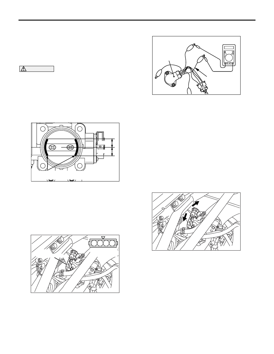
1. Remove the air intake hose from the throttle body.
2. Spray cleaning fluid on a clean cloth.

CAUTION

• Do not spray the cleaning fluid directly to the 

throttle valve.

• Make sure the cleaning fluid does not enter 

the motor from the bypass line. Also make 
sure it does not enter the sensor through the 
shaft.

• Be careful not to rub off the molybden applied 

around the throttle valve shaft.

3. Wipe off the dirt around the throttle valve with the 

cloth sprayed with cleaning fluid.

4. Attach the air intake hose.
5. Adjust the basic idle speed (Refer to 

P.13A-396

).

THROTTLE POSITION SENSOR 
ADJUSTMENT

M1131001100801

1. Connect the M.U.T.-II/III to the diagnosis 

connector.
When not using the M.U.T.-II/III, proceed as 
follows.

(1) Disconnect the throttle position sensor 

connector and connect the special tool test 
harness (MB991536) between the 
disconnected connector taking care not to 
confuse the terminal to be connected.

(2) Connect digital voltmeter between the terminal 

No. 2 (special tool’s yellow clip on the sensor 
output) and the terminal No. 4 (special tool’s 
red clip on the sensor earth) of the throttle 
position sensor connector.

2. Turn the ignition switch to "ON" position (but do 

not start the engine).

3. Check the output voltage of the throttle position 

sensor.

Standard value: 535 

 735 mV

4. If not within the standard value, loosen the throttle 

position sensor mounting bolts. Then rotate the 
sensor body to adjust.

5. Turn the ignition switch to "LOCK" (OFF) position.
6. Remove the M.U.T.-II/III. If the M.U.T.-II/III is not 

used, remove the special tool, and then connect 
the throttle position sensor connector.

7. If a diagnosis code is displayed, erase the 

diagnosis code by using the M.U.T.-II/III or 
disconnect the negative battery cable from the 
battery terminal and then leave it for at least 10 
seconds. After that, reconnect the battery cable, 
and then let the engine run at idle for 
approximately 10 minutes.

AK000833AD

15 mm

15 mm

Areas on throttle valve to
apply molybdenum disulfide

AK304568

1

2 3

4

AB

Equipment 
side connector

Throttle 
position sensor

AK201752AB

MB991536

Throttle position
sensor

AK304569AB

ON-VEHICLE SERVICE

MULTIPORT FUEL INJECTION (MPI)

13A-396

BASIC IDLE SPEED ADJUSTMENT

M1131001800888

CAUTION

• The standard idling speed has been adjusted 

by the speed adjusting screw (SAS) by the 
manufacturer, and there should usually be no 
need for readjustment.

• If the adjustment has been changed by mis-

take, the idle speed may become too high or 
the idle speed may drop too low when loads 
from components such as the A/C are placed 
on the engine. If this occurs, adjust by the fol-
lowing procedure.

• The adjustment, if made, should be made 

after first confirming that the spark plugs, the 
injectors, the idle speed control servo, the 
compression pressure, etc., are all normal.

1. Before inspection and adjustment, set the vehicle 

to the pre-inspection condition.

2. Connect the M.U.T.-II/III to the diagnosis 

connector (16-pin).
NOTE: When the M.U.T.-II/III is connected, the 
diagnosis control terminal should be earthed.

3. Start the engine and run at idle.
4. Select the item No. 30 of the M.U.T.-II/III Actuator 

test.
NOTE: This holds the idle speed control servo at 
the basic step to adjust the basic idle speed.

5. Check the idle speed.

Standard value:

800 

± 50 r/min

NOTE: 

.

The engine speed may be 20 to 100 r/min 
lower than indicated above for a new vehicle 
[driven approximately 500 km or less], but no 
adjustment is necessary.

If the engine stalls or the engine speed is low 
even though the vehicle has been driven 
approximately 500 km or more, it is probable 
that deposits are adhered to the throttle valve, 
so clean it (Refer to 

P.13A-395

).

6. If not within the standard value range, turn the 

speed adjusting screw (SAS) to make the 
necessary adjustment.
NOTE: If the idling speed is higher than the stand-
ard value range even when the SAS is fully 
closed, check whether or not there is any indica-
tion that the fixed SAS has been moved. If there is 
an indication that it has been moved, adjust the 
fixed SAS.

7. Press the M.U.T.-II/III clear key, and release the 

idle speed control servo from the Actuator test 
mode.
NOTE: Unless the idle speed control servo is 
released, the Actuator test mode will continue 27 
minutes.

8. Turn the ignition switch to "LOCK" (OFF) position.
9. Disconnect the M.U.T.-II/III.
10.Start the engine again and let it run at idle speed 

for about 10 minutes; check that the idling 
condition is normal.

FUEL PRESSURE TEST

M1131001901286

1. Release residual pressure from the fuel pipe line 

to prevent fuel gush out (Refer to 

P.13A-398

).

CAUTION

Cover the hose connection with rags to prevent 
splash of fuel that could be caused by some 
residual pressure in the fuel pipe line.

2. Disconnect the high-pressure fuel hose at the 

delivery pipe side.

AK304570 AB

Speed adjust screw

AK304571AB

High-pressure
fuel hose

ON-VEHICLE SERVICE

MULTIPORT FUEL INJECTION (MPI)

13A-397

3. Assemble the fuel pressure measurement tools 

as follows.

<When using the fuel pressure gauge set (special 

tool)>

a. Remove the union joint and bolt from the special 

tool adaptor hose (MD998709) and attach the 
special tool hose adaptor (MD998742) to the 
adaptor hose.

b. Via a gasket, install the special tool fuel pressure 

gauge set (MB991637 or MB991981) into the 
special tool that has already assembled as 
described in (a) above.

<When using the fuel pressure gauge>

a. Remove the union joint and bolt from special tool 

adaptor hose (MD998709) and attach the special 
tool hose adaptor (MD998742) to the adaptor 
hose.

b. Via a suitable O-ring or gasket, install the fuel 

pressure gauge to the special tool that has 
already assembled as described in (a) above.

4. Install the assembled fuel pressure measurement 

tools between the fuel rail and fuel high-pressure 
hose.

CAUTION

To prevent damage to the M.U.T.-II/III, always turn 
the ignition switch to the "LOCK" (OFF) position 
before connecting or disconnecting the 
M.U.T.-II/III.
5. Connect the M.U.T.-II/III to the diagnosis 

connector.

6. Turn the ignition switch to "ON" position (But do 

not start the engine).

7. Select "Item No. 07" from the M.U.T.-II/III Actuator 

test to drive the fuel pump. Check that there are 
no fuel leaks from any parts.

8. Finish the actuator test or turn the ignition switch 

to "LOCK" (OFF) position.

9. Start the engine and run at idle.
10.Measure fuel pressure while the engine is running 

at idle.

Standard value: Approximately 230 kPa

11.Disconnect the vacuum hose from the fuel 

pressure regulator and measure fuel pressure 
with the hose end closed by a finger.

Standard value: 289 

 309 kPa

12.Check to see that fuel pressure at idle does not 

drop even after the engine has been raced 
several times.

AKX01458 AG

MB 991637

Gasket

MD 998709

MD 998742

High-pressure
fuel hose

Delivery
pipe

AK305430AB

MB 991981

Gasket

MD 998709

MD 998742

High-pressure
fuel hose

Delivery
pipe

AKX01457AF

MD 998742

MD 998709

O-ring or gasket

Fuel pressure 
gauge set

High-pressure
fuel hose

Delivery
pipe

AK304572AB

Vacuum hose

Fuel pressure
regulator

ON-VEHICLE SERVICE

MULTIPORT FUEL INJECTION (MPI)

13A-398

13.Racing the engine repeatedly, hold the fuel return 

hose lightly with fingers to feel that fuel pressure 
is present in the return hose.
NOTE: If the fuel flow rate is low, there will be no 
fuel pressure in the return hose.

14.If any of fuel pressure measured in steps 10 to 13 

is out of specification, troubleshoot and repair 
according to the table below.

15.Stop the engine and check change of fuel 

pressure gauge reading. Normal if the reading 
does not drop within 2 minutes. If it does, observe 
the rate of drop and troubleshoot and repair 
according to the table below.

16.Release residual pressure from the fuel pipe line 

(Refer to 

P.13A-398

).

CAUTION

Cover the hose connection with rags to prevent 
splash of fuel that could be caused by some 
residual pressure in the fuel pipe line.
17.Remove the fuel pressure gauge and special tool 

from the delivery pipe.

18.Replace the O-ring at the end of the fuel high 

pressure hose with a new one. Furthermore, 
apply engine oil to the new O-ring before 
replacement.

19.Fit the fuel high pressure hose over the delivery 

pipe and tighten the bolt to specified toque.

Tightening torque: 5.0 

± 1.0 Nm

20.Check for any fuel leaks by following the 

procedure in step 7.

21.Disconnect the M.U.T.-II/III.

FUEL PUMP CONNECTOR 
DISCONNECTION (HOW TO REDUCE 
PRESSURIZED FUEL LINES)

M1131000900718

WARNING

When removing the fuel pipe, etc., release 
fuel pressure to prevent fuel spray.

1. Remove the rear seat assembly (Refer to GROUP 

52A 

− Rear Seat Assembly 

P.52A-20

).

2. Remove the protector.

Symptom

Probable cause

Remedy

• Fuel pressure too low

• Fuel pressure drops after racing

• No fuel pressure in fuel return 

hose

Clogged fuel filter

Replace fuel filter

Fuel leaking to return side due to 
poor fuel regulator valve seating or 
settled spring

Replace fuel pressure regulator

Low fuel pump delivery pressure

Replace fuel pump

Fuel pressure too high

Binding valve in fuel pressure 
regulator

Replace fuel pressure regulator

Clogged fuel return hose or pipe

Clean or replace hose or pipe

Same fuel pressure when vacuum 
hose is connected and when 
disconnected

Damaged vacuum hose or 
Clogged nipple

Replace vacuum hose or clean 
nipple

Symptom

Probable cause

Remedy

Fuel pressure drops gradually after 
engine is stopped

Leaky injector

Replace injector

Leaky fuel regulator valve seat

Replace fuel pressure regulator

Fuel pressure drops sharply 
immediately after engine is 
stopped

Check valve in fuel pump is held 
open

Replace fuel pump

Y0915AU

Y2015AU

AC208407

Fuel pump module connector

AB


Content   ..  478  479  480  481   ..