Mitsubishi Lancer Evolution IX. Manual - part 479
 

  Index      Mitsubishi     Mitsubishi Lancer Evolution IX - service repair manual


Search            


Content   ..  477  478  479  480   ..


Mitsubishi Lancer Evolution IX. Manual - part 479


TROUBLESHOOTING

MULTIPORT FUEL INJECTION (MPI)

13A-391

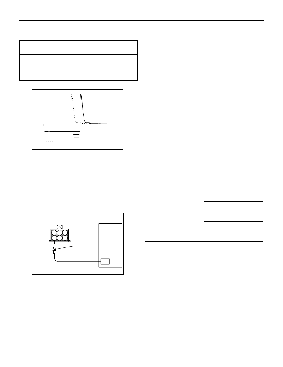
Wave Pattern Observation Points

Point A: Height of solenoid back electromotive force

Point B: Injector drive time

The injector drive time will be synchronized with the 

M.U.T.-II/III tester display.

• When the engine is suddenly raced, the drive 

time will be greatly extended at first, but the drive 
time will soon match the engine speed.

IDLE SPEED CONTROL (ISC) SERVO 
(STEPPER MOTOR)
Measurement Method

1. Disconnect the idle speed control servo 

connector, and connect the special tool test 
harness (MB991709) in between.

2. Connect the oscilloscope special patterns pickup 

to the idle speed control servoside connector 
terminal No. 1, No. 3, No. 4 and No. 6 
respectively.

Alternate Method (Test harness not 
available)

1. Connect the oscilloscope special patterns pickup 

to engine-ECU terminal No. 14, connection 
terminal No. 28, connection terminal No. 15, and 
connection terminal No. 29 respectively.

Standard Wave Pattern

Observation conditions

Contrast with standard 
wave pattern

Probable cause

Solenoid coil back 
electromotive force is 
low or doesn't appear at 
all.

Short in the injector 
solenoid

AKX01605AE

When idling
When racing

1 2 3

5

4

6

AK201856AB

Special
patterns
pickup

Oscilloscope

Function

Special patterns

Pattern height

High

Pattern selector

Display

Engine condition

When the engine coolant 
temperature is 20

°C or 

below, turn the ignition 
switch from "LOCK" 
(OFF) position to ON 
(without starting the 
engine).
While the engine is 
idling, turn the A/C 
switch to ON.
Immediately after 
starting the warm 
engine.

TROUBLESHOOTING

MULTIPORT FUEL INJECTION (MPI)

13A-392

Wave pattern Observation Points

Check that the standard wave pattern appears when 
the stepper motor is operating.
Point A: Presence or absence of induced electromo-
tive force from the motor turning (Refer to the abnor-
mal wave pattern).

Point B: Height of coil reverse electromotive force

Examples of Abnormal Wave Pattern

Example 1

Cause of problem
Motor is malfunctioning. (Motor is not operating.)
Wave pattern characteristics
Induced electromotive force from the motor turn-

ing does not appear.

Example 2

Cause of problem
Open circuit in the line between the stepper 

motor and the engine-ECU.

Wave pattern characteristics
Current is not supplied to the motor coil on the 

open circuit side (Voltage does not drop to 0 
V).

Furthermore, the induced electromotive force 

waveform at the normal side is slightly differ-
ent from the normal waveform.

AK201857

30

20

10

(V)

Stepper
motor
control
signal
wave
pattern

The wave pattern
appears for an
instant, but soon
disappears.

Point B
Coilreverse electromotive
force (Approx.3x10V)

Standard wave pattern

Point A
Induced electromotive force
from the motor turning

Time

AB

Contrast with standard wave 
pattern

Probable 
cause

Induced electromotive force does 
not appear or is extremely small.

Motor is 
malfunctioning

Contrast with standard wave 
pattern

Probable 
cause

Coil reverse electromotive force 
does not appear or is extremely 
small.

Short in the 
coil

AKX01608AE

AKX01609AF

Open
circuit
side

Normal
side

TROUBLESHOOTING

MULTIPORT FUEL INJECTION (MPI)

13A-393

IGNITION COIL AND POWER TRANSIS-
TOR
Measurement Method

1. Disconnect the ignition coil connector, and 

connect the special tool test harness (MB991348) 
in between (All terminals should be connected).

2. Connect the oscilloscope special patterns pickup 

to terminal No. 3 of each ignition coil connector in 
turn.

Alternate Method (Test harness not 
available)

1. Connect the oscilloscope special patterns pickup 

to engine-ECU terminal No. 11 (No. 1 

− No. 4), 

connection terminal No. 12 (No. 2 

− No.3) 

respectively.

Standard Wave Pattern

Observation condition

AK201750

1 2 3

CH1

AB

Special
patterns
pickup

Oscilloscope

Function

Special patterns

Pattern height

Low

Pattern selector

Display

Engine r/min

Approximately 1,200 
r/min

AK204435

2

2

0

0

4

4

6

(V)

Crank angle
sensor output
wave pattern

Power transistor
control signal
wave pattern

75˚ BTDC

5˚ BTDC

T

Compression top dead center

T1

T1 : Time computed by the engine-ECU

T : Revolution time corresponding to a crank angle of 180˚

Ignition period

OFF

ON

Dwell section

   : Spark advance angle

AC

Standard wave pattern

TROUBLESHOOTING

MULTIPORT FUEL INJECTION (MPI)

13A-394

Wave Pattern Observation Points

Point: Condition of wave pattern build-up section and 
maximum voltage (Refer to abnormal wave pattern 
examples 1 and 2).

Examples of Abnormal Wave Patterns

Example 1
Wave pattern during engine cranking

Cause of problem
Open-circuit in ignition primary circuit
Wave pattern characteristics
Top-right part of the build-up section cannot be 

seen, and voltage value is approximately 2 V 
too low.

Example 2
Wave pattern during engine cranking

Cause of problem
Malfunction in power transistor
Wave pattern characteristics
Power voltage results when the power transistor 

is ON.

Condition of wave pattern 
build-up section and maximum 
voltage

Probable cause

Rises from approximately 2 V 
to approximately 4.5 V at the 
top-right

Normal

2 V rectangular wave

Open-circuit in 
ignition primary 
circuit

Rectangular wave at power 
voltage

Power transistor 
malfunction

AKX01612AD

Normal wave pattern

2V

AKX01613AD

Normal wave pattern

V

B


Content   ..  477  478  479  480   ..