Mitsubishi Lancer Evolution IX. Manual - part 464
TROUBLESHOOTING
MULTIPORT FUEL INJECTION (MPI)
13A-331
OPERATION
• The battery voltage is applied on the engine-ECU
(terminal No. 31) form the condenser fan control
relay (low).
• The battery is applied on the engine-ECU (termi-
nal No. 30) from the condenser fan control relay
(high).
FUNCTION
• The engine-ECU condenser fan control relay
turns "ON" with the signal from the engine-ECU,
and power is supplied to the condenser fan
motor.
PROBABLE CAUSES
• Failed condenser fan relay (high)
• Failed condenser fan relay (low)
• Failed condenser fan motor
• Open/short circuit in condenser fan control relay
circuit or loose connector contact
• Failed engine-ECU
DIAGNOSIS PROCEDURE
NOTE:
.
*1: L.H. drive vehicles
*2: R.H. drive vehicles
STEP 1. Check condenser fan motor.
• Check condenser fan motor (Refer to GROUP 55
− Heater, Air conditioner and Ventilation
−Condenser and condenser fan motor − Inspec-
tion
).
Q: Is the check result normal?
YES :
Go to Step 2 .
NO :
Replace the condenser fan motor.
STEP 2. M.U.T.-II/III actuator test
• Item No. 38: Condenser fan (low)
OK: Condenser fan motor rotates (low)
Q: Is the check result normal?
YES :
Go to Step 3 .
NO :
Go to Step 14 .
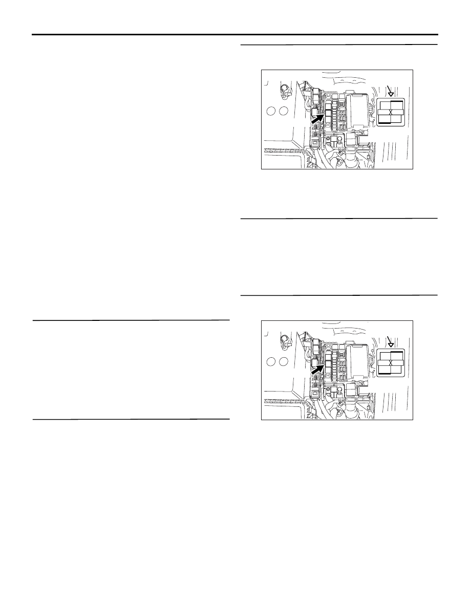
STEP 3. Connector check: A-06X condenser fan
relay (low) connector.
Q: Is the check result normal?
YES :
Go to Step 4 .
NO :
Repair or replace the connector.
STEP 4. Check condenser fan relay (low).
• Check condenser fan relay (low) (Refer to
GROUP 55
− On-vehicle Service
Q: Is the check result normal?
YES :
Go to Step 5 .
NO :
Replace the condenser fan relay (low).
STEP 5. Perform voltage measurement at A-06X
condenser fan relay (low) connector.
• Remove relay, and measure at relay box side.
• Ignition switch: "ON"
• Voltage between terminal No. 2 and earth.
OK: System voltage
Q: Is the check result normal?
YES :
Go to Step 8 .
NO :
Go to Step 6 .
AK305265
2
1
3
4
Relay box's
triangle marks
AB
A-06X
Harness side
connector
Connector: A-06X
AK305265
2
1
3
4
Relay box's
triangle marks
AB
A-06X
Harness side
connector
Connector: A-06X