Mitsubishi Lancer Evolution IX. Manual - part 463
 

  Index      Mitsubishi     Mitsubishi Lancer Evolution IX - service repair manual


Search            


Content   ..  461  462  463  464   ..


Mitsubishi Lancer Evolution IX. Manual - part 463


TROUBLESHOOTING

MULTIPORT FUEL INJECTION (MPI)

13A-327

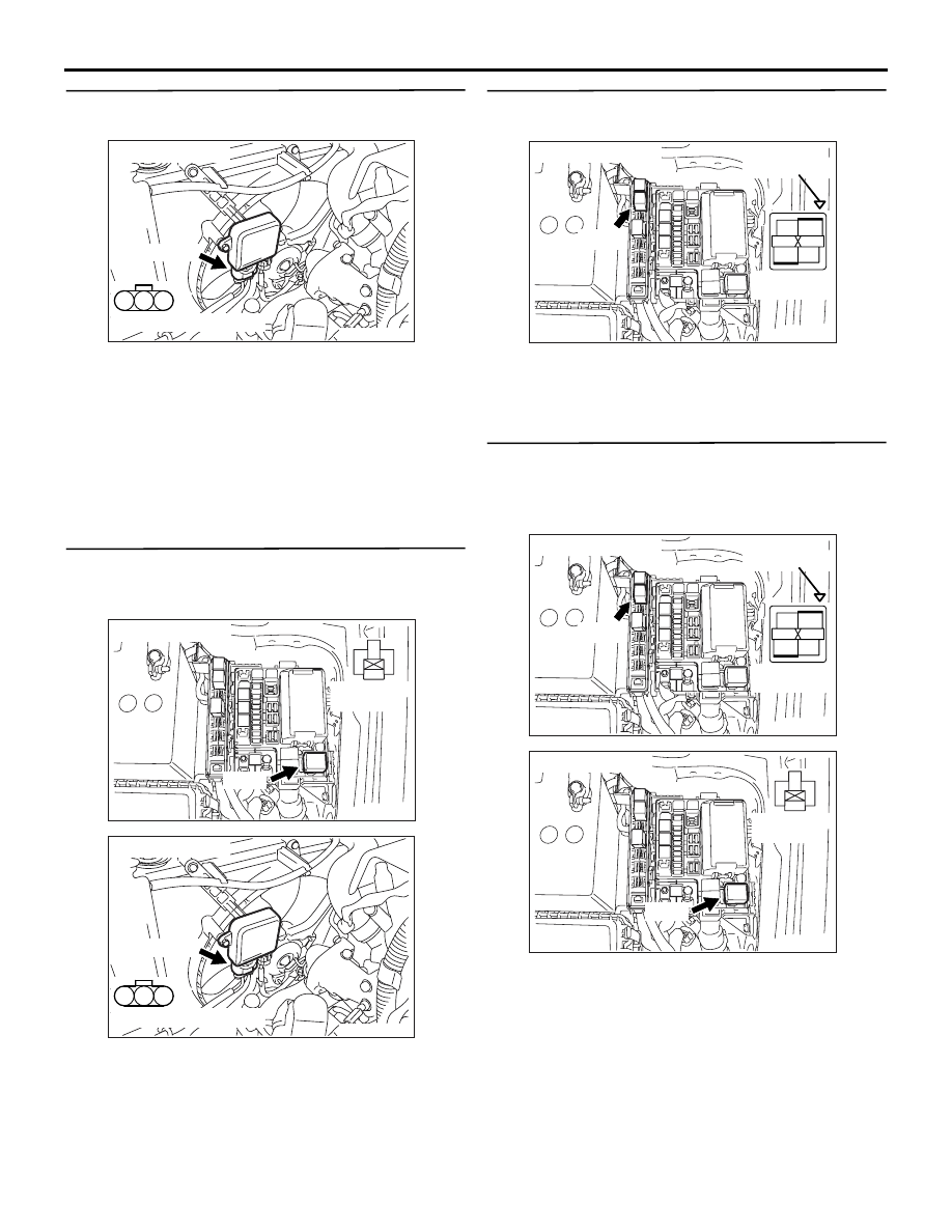
STEP 8. Perform voltage measurement at A-17 
fan controller connector.

• Disconnect connector, and measure at harness 

side.

• Ignition switch: "ON"

• Voltage between terminal No. 3 and earth.

OK: System voltage

Q: Is the check result normal? 

YES : 

Go to Step 12 .

NO : 

Go to Step 9 .

STEP 9. Check harness between A-09X (terminal 
No. 2) radiator fan control relay connector and 
A-17 (terminal No. 3) fan controller connector.

• Check output line for open/short circuit.

Q: Is the check result normal?

YES : 

Go to Step 10 .

NO : 

Repair the damaged harness wire.

STEP 10. Connector check: B-12X engine control 
relay connector

Q: Is the check result normal? 

YES : 

Go to Step 11 .

NO : 

Repair or replace the connector.

STEP 11. Check harness between B-12X (terminal 
No. 4) engine control relay connector and A-09X 
(terminal No. 1) radiator fan control relay 
connector.

NOTE: Before checking harness, check intermediate 
connectors A-13*

1

 or C-31*

2

 and C-105, and repair if 

necessary.

• Check power supply line for damage.

Q: Is the check result normal?

YES : 

Check and repair harness between A-09X 

(terminal No. 3) radiator fan control relay 
connector and body earth.

• Check earthing line for damage.

NO : 

Repair the damaged harness wire.

AK305256

1

2

3

AB

Connector: A-17

A-17 (GR)

Harness side connector

AK305263

3

1

2

4

AB

A-09X

Harness side
connector

Connector: A-09X

AK305256

1

2

3

AB

Connector: A-17

A-17 (GR)

Harness side connector

AK305003

2

1

3

4

AB

Connector : B-12X

B-12X

Harness side 
connector

Relay box’s
triangle marks

AK305003

2

1

3

4

AB

Connector : B-12X

B-12X

Harness side 
connector

Relay box’s
triangle marks

AK305263

3

1

2

4

AB

A-09X

Harness side
connector

Connector: A-09X

TROUBLESHOOTING

MULTIPORT FUEL INJECTION (MPI)

13A-328

STEP 12. Connector check: C-121 engine-ECU 
connector

Q: Is the check result normal? 

YES : 

Go to Step 13 .

NO : 

Repair or replace the connector.

STEP 13. Check radiator fan motor drive.

• Disconnect C-121 engine-ECU connector.

• Ignition switch: "ON"

OK: Radiator fan motor rotates at a high 
speed

Q: Is the check result normal? 

YES : 

Go to Step 14 .

NO : 

Go to Step 15 .

STEP 14. M.U.T.-II/III actuator test

• Item No. 21: Fan controller

OK: Radiator fan motor rotates

Q: Is the check result normal?

YES : 

Intermittent malfunction (Refer to GROUP 

00 

− How to Use 

Troubleshooting/Inspection Service Points 

P.00-5

.)

NO : 

Replace the engine-ECU.

STEP 15. Perform voltage measurement at C-121 
engine-ECU connector.

• Disconnect connector, and measure at harness 

side.

• Ignition switch: "ON"

• Voltage between terminal No. 18 and earth.

OK: 4.9 

 5.1 V

Q: Is the check result normal? 

YES : 

Go to Step 16 .

NO : 

Go to Step 18 .

AK501995

2

3

4

5

6

7

8

9

11

12

13

14

15

16

17

18

19

20

30

21

22

23

24

25

26

27

28

29

31

32

33

34

35

1

10

AB

Connector: C-121

C-121 (GR)

C-121 (GR)

Harness side connector

<L. H. drive vehicles>

<R. H. drive vehicles>

AK501995

2

3

4

5

6

7

8

9

11

12

13

14

15

16

17

18

19

20

30

21

22

23

24

25

26

27

28

29

31

32

33

34

35

1

10

AB

Connector: C-121

C-121 (GR)

C-121 (GR)

Harness side connector

<L. H. drive vehicles>

<R. H. drive vehicles>

TROUBLESHOOTING

MULTIPORT FUEL INJECTION (MPI)

13A-329

STEP 16. Check harness between A-09X 
(terminal No. 4) radiator fan control relay 
connector and battery.

• Check power supply line for damage.

Q: Is the check result normal? 

YES : 

Go to Step 17 .

NO : 

Repair the damaged harness wire.

STEP 17. Check harness between A-09X 
(terminal No. 2) radiator fan control relay 
connector and A-17 (terminal No. 3) fan 
controller connector.

• Check output line for damage.

Q: Is the check result normal? 

YES : 

Replace the radiator fan motor and fan 

controller.

NO : 

Repair the damaged harness wire.

STEP 18. Check harness between A-17 (terminal 
No. 2) fan controller connector and C-121 
(terminal No. 18) engine-ECU connector.

NOTE: Before checking harness, check intermediate 
connectors A-13*

1

 or C-31*

2

 and repair if necessary.

• Check output line for short circuit.

Q: Is the check result normal?

YES : 

Replace the radiator fan motor and fan 

controller.

NO : 

Repair the damaged harness wire.

AK305263

3

1

2

4

AB

A-09X

Harness side
connector

Connector: A-09X

AK305263

3

1

2

4

AB

A-09X

Harness side
connector

Connector: A-09X

AK305256

1

2

3

AB

Connector: A-17

A-17 (GR)

Harness side connector

AK305256

1

2

3

AB

Connector: A-17

A-17 (GR)

Harness side connector

AK501995

2

3

4

5

6

7

8

9

11

12

13

14

15

16

17

18

19

20

30

21

22

23

24

25

26

27

28

29

31

32

33

34

35

1

10

AB

Connector: C-121

C-121 (GR)

C-121 (GR)

Harness side connector

<L. H. drive vehicles>

<R. H. drive vehicles>

TROUBLESHOOTING

MULTIPORT FUEL INJECTION (MPI)

13A-330

Inspection Procedure 26: Condenser Fan Relay System

1

2

3

4

1

2

3

4

AK501831

1 2

1

2

1 2 3
4 5 6

2

3 4

5 6

7 8

9

11 12 13 14 15 16 17 18 19 20

30

21 22 23

24 25

26 27 28 29

3132 33

34 35

1

10

Condenser fan relay system

Battery

W

W

B-R

B-R

30A

30A

Condenser
fan relay
(high)

A-07X

4

1

2

3

W

A-06X

4

1

Condenser
fan relay (low)

L-B

17 (*1) or 10 (*2)

16*1

10*2

J/B

J/B (2)
C-101

2

C-208

4

W-B

W-B

7.5A

B-Y

B

G-R

Condenser
fan motor

A-34

MU802601

A-35

MU802661

1

2

2

W-B

G-R

C-121

(MU803784)

2

3

31

30

5<A-29> (

*1)

16<C-31> (

*2)

1<A-29> (

*1)

7<C-31> (

*2)

Engine-ECU

Wire colour code
B: Black  LG: Light green  G: Green  L: Blue  W: White  Y: Yellow  SB: Sky blue  BR: Brown  O: Orange  GR: Gray
R: Red  P: Pink  V: Violet  PU: Purple

NOTE

*1: L.H. drive vehicles
*2: R.H. drive vehicles

AB

L

Ignition switch

IG2

ST

LOCK

ACC

IG1

R

11

5

25

W-B

C-211

13

2

C-210

C-129


Content   ..  461  462  463  464   ..