Mitsubishi Lancer Evolution IX. Manual - part 447
 

  Index      Mitsubishi     Mitsubishi Lancer Evolution IX - service repair manual


Search            


Content   ..  445  446  447  448   ..


Mitsubishi Lancer Evolution IX. Manual - part 447


TROUBLESHOOTING

MULTIPORT FUEL INJECTION (MPI)

13A-263

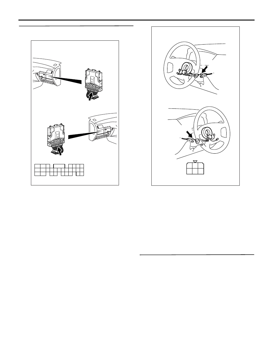
STEP 9. Connector check: C-119 engine-ECU 
connector

Q: Is the check result normal?

YES : 

Check intermediate connector C-123, and 

repair if necessary. If intermediate 
connector is normal, check and repair 
harness between C-208 (terminal No. 9) 
ignition switch connector and C-119 
(terminal No. 68) engine-ECU connector.

• Check output line for open/short 

circuit.

NO : 

Repair or replace the connector.

STEP 10. M.U.T.-II/III data list

• Refer to Data List Reference Table 

P.13A-372

.

a. Item No. 22: Crank angle sensor 

Q: Is the check result normal?

YES : 

Go to Step 11 .

NO : 

Check crank angle sensor system (Refer to 
Code No. P0335 

P.13A-155

).

AK501994

65

43
50

42
49

41
48
60

61

64

46

47

58

59

67

68

45

56
66

52 51

44

53

62

54

63

57

55

AB

Connector: C-119

C-119 (GR)

C-119 (GR)

Harness side connector

<L. H. drive vehicles>

<R. H. drive vehicles>

AK305251

1

2

3

4

5

6

Harness side connector

Connector: C-208

C-208

<L. H. drive vehicles>

<R. H. drive vehicles>

C-208

AB

TROUBLESHOOTING

MULTIPORT FUEL INJECTION (MPI)

13A-264

STEP 11. Check injector for operating sound.

• Check injector for operating sound (Refer to 

P.13A-406

).

Q: Can operating sound be heard? 

YES : 

Go to Step 12 .

NO : 

Check the injector system of the defective 

cylinder

(Refer to Code No. 0201: No. 1 injector system 

P.13A-105

).

(Refer to Code No. 0202: No. 2 injector system 

P.13A-111

).

(Refer to Code No. 0203: No. 3 injector system 

P.13A-117

).

(Refer to Code No. 0204: No. 4 injector system 

P.13A-123

).

STEP 12. Check ignition coil spark

Q: Is the check result normal?

YES : 

Go to Step 13 .

NO : 

Check ignition circuit system (refer to 
inspection procedure 30 <L. H. drive 
vehicles>

P.13A-356

 or inspection 

procedure 31 <R. H. drive 
vehicles>

P.13A-363

).

STEP 13. Replace the engine-ECU.

• After replacing the engine-ECU, re-check the 

trouble symptoms.

Q: Does trouble symptom persist? 

YES : 

Check for foreign matters (water, kerosene, 

etc.) in fuel and replace if necessary. 

NO : 

The check is end.

Inspection Procedure 7: Starting Impossible (Initial Combustion but no Complete Combustion),  
Starting (Long Time to Start)

COMMENTS ON TROUBLE SYMPTOM

• Failure is possibly caused by poor ignition, incor-

rect air-fuel ratio at cranking, improper fuel pres-
sure or other faults.

PROBABLE CAUSES

• Failed battery

• Failed ignition system

• Failed fuel system

• Failed air-fuel ratio control system

• Failed idle speed control system

• Failed intake system

• Failed exhaust gas cleaning system

• Throttle valve fouled around

• Timing belt not in place

• Compression pressure improper

• Failed engine-ECU

DIAGNOSIS PROCEDURE

STEP 1. Check battery condition.

Q: Have the battery terminal been disconnected? 

YES : 

After warm-up engine, idle for about 10 

minutes.

NO : 

Go to Step 2 .

STEP 2. Check battery voltage.

• Measure battery voltage at cranking.

OK: 8 V or higher 

Q: Is the check result normal?

YES : 

Go to Step 3 .

NO : 

Check battery (Refer to GROUP 54A 

− 

Battery 

− On-vehicle Service − Battery Test 

P.54A-5

).

STEP 3. M.U.T.-II/III diagnosis code

Q: Diagnosis code set?

YES : 

Inspection chart for diagnosis codes (Refer 

to 

P.13A-17

).

NO : 

Go to Step 4 .

STEP 4. M.U.T.-II/III data list

• Refer to Data List Reference Table 

P.13A-372

.

a. Item No. 13: Intake air temperature sensor 
b. Item No. 21: Engine coolant temperature sen-

sor 

c. Item No. 25: Barometric pressure sensor

Q: Are the check results normal?

YES : 

Go to Step 5 .

NO : 

Perform the diagnosis code classified check 
procedure for the sensor that has shown an 
abnormal data value (Refer to Inspection 
Chart for Diagnosis Codes 

P.13A-17

).

TROUBLESHOOTING

MULTIPORT FUEL INJECTION (MPI)

13A-265

STEP 5. Check start ability.

• With depressing the accelerator pedal slightly, 

and start the engine. 

Q: Is the start ability good?

YES : 

Go to Step 6 .

NO : 

Go to Step 7 .

STEP 6. Check idle speed control servo for 
operating sound.

• Check idle speed control servo for operating 

sound (Refer to 

P.13A-408

).

Q: Is the check result normal?

YES : 

Clean throttle body (throttle valve portion) 

(Refer to 

P.13A-395

).

NO : 

Check idle speed control servo system 
(Refer to Code No. P0505 

P.13A-190

).

STEP 7. M.U.T.-II/III actuator test

• Refer to Actuator Test Reference Table 

P.13A-378

.

a. Item No. 07: Fuel pump

OK: Operating sound of fuel pump can be 
heard.

Q: Is the check result normal?

YES : 

Go to Step 8 .

NO : 

Check fuel pump system (Refer to 
Inspection Procedure 24 

P.13A-313

).

STEP 8. Check air intake from intake hose and 
intake manifold.

Q: Is the check result normal?

YES : 

Go to Step 9 .

NO : 

Repair.

STEP 9. Check injector for operating sound.

• Check injector for operating sound at engine 

cranking (Refer to 

P.13A-406

).

Q: Can operating sound be heard?

YES : 

Go to Step 10 .

NO : 

Check the injector system of the defective 

cylinder

(Refer to Code No. 0201: No. 1 injector system 

P.13A-105

).

(Refer to Code No. 0202: No. 2 injector system 

P.13A-111

).

(Refer to Code No. 0203: No. 3 injector system 

P.13A-117

).

(Refer to Code No. 0204: No. 4 injector system 

P.13A-123

).

STEP 10. Check timing marks of timing belt.

Q: Is the check result normal?

YES : 

Go to Step 11 .

NO : 

Align timing marks.

STEP 11. Perform voltage measurement at C-119 
engine-ECU connector.

• Measure engine-ECU terminal voltage.

• Voltage between terminal No. 46 and earth also 

between terminal No. 58 and earth.

OK: System voltage

Q: Is the check result normal?

YES : 

Go to Step 13 .

NO : 

Go to Step 12 .

AK501994

65

43
50

42
49

41
48
60

61

64

46

47

58

59

67

68

45

56
66

52 51

44

53

62

54

63

57

55

AB

Connector: C-119

C-119 (GR)

C-119 (GR)

Harness side connector

<L. H. drive vehicles>

<R. H. drive vehicles>

TROUBLESHOOTING

MULTIPORT FUEL INJECTION (MPI)

13A-266

STEP 12. Connector check: C-119 engine-ECU 
connector

Q: Is the check result normal?

YES : 

Check and repair harness between C-119 

(terminal No. 46 and No. 58) engine-ECU 
connector and body earth.

• Check earth line for open circuit and 

damage.

NO : 

Repair or replace the connector.

STEP 13. Connector check: B-103 and B-114 
ignition coil connectors.

Q: Is the check result normal?

YES : 

Go to Step 14 .

NO : 

Repair or replace the connector.

STEP 14. Check ignition coil spark.

Q: Is the check result normal?

YES : 

Go to Step 19 .

NO : 

Go to Step 15 .

STEP 15. Check spark plug.

Q: Is the check result normal?

YES : 

Go to Step 16 .

NO : 

Replace the spark plug.

STEP 16. Check spark plug cable itself.

• Check spark plug cable itself (Refer to GROUP 

16 

− Ignition System − On-vehicle Service 

P.16-29

).

Q: Is the check result normal?

YES : 

Go to Step 17 .

NO : 

Replace the spark plug cable.

STEP 17. Check ignition coil itself.

• Check ignition coil itself (Refer to GROUP 16 − 

Ignition System 

 On-vehicle Service 

P.16-28

).

Q: Is the check result normal?

YES : 

Go to Step 18 .

NO : 

Replace the ignition coil.

AK501994

65

43
50

42
49

41
48
60

61

64

46

47

58

59

67

68

45

56
66

52 51

44

53

62

54

63

57

55

AB

Connector: C-119

C-119 (GR)

C-119 (GR)

Harness side connector

<L. H. drive vehicles>

<R. H. drive vehicles>

AK305047

1

2

3

Connector : B-103, B-114

B-114(GR)

B-103(GR)

AB

Harness side 
connector


Content   ..  445  446  447  448   ..