Mitsubishi Lancer Evolution IX. Manual - part 446
 

  Index      Mitsubishi     Mitsubishi Lancer Evolution IX - service repair manual


Search            


Content   ..  444  445  446  447   ..


Mitsubishi Lancer Evolution IX. Manual - part 446


TROUBLESHOOTING

MULTIPORT FUEL INJECTION (MPI)

13A-259

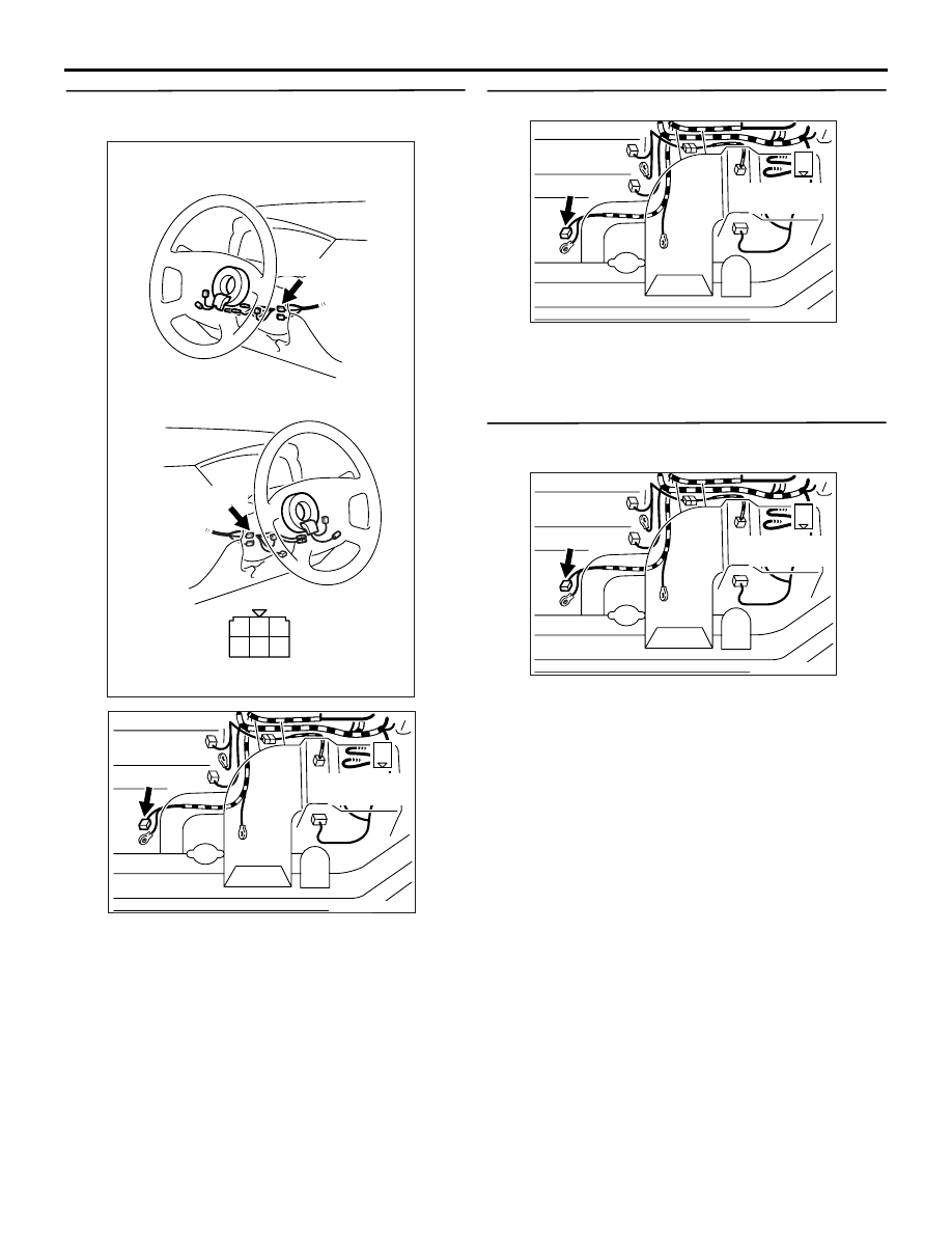
STEP 7. Connector check: C-208 ignition switch 
connector and B-21 starter connector

Q: Is the check result normal?

YES : 

Check intermediate connectors C-123 and 

B-14, and repair if necessary. If intermediate 
connectors are normal, check and repair 
harness between C-208 (terminal No. 5) 
ignition switch connector and B-21 (terminal 
No. 1) starter connector.

• Check output line for short circuit.

NO : 

Repair or replace the connector.

STEP 8. Connector check: B-21 starter connector

Q: Is the check result normal?

YES : 

Go to Step 9 .

NO : 

Repair or replace the connector.

STEP 9. Perform voltage measurement at B-21 
starter connector.

• Disconnect connector, and measure at the har-

ness side.

• Ignition switch: ST

• Voltage between terminal No. 1 and earth.

OK: System voltage

Q: Is the check result normal?

YES : 

Go to Step 11 .

NO : 

Go to Step 10 .

AK305251

1

2

3

4

5

6

Harness side connector

Connector: C-208

C-208

<L. H. drive vehicles>

<R. H. drive vehicles>

C-208

AB

AK305254

1

B-21(B)

AB

Harness side 
connector

Connector: B-21

AK305254

1

B-21(B)

AB

Harness side 
connector

Connector: B-21

AK305254

1

B-21(B)

AB

Harness side 
connector

Connector: B-21

TROUBLESHOOTING

MULTIPORT FUEL INJECTION (MPI)

13A-260

STEP 10. Connector check: C-208 ignition switch 
connector

Q: Is the check result normal?

YES : 

Check intermediate connectors B-14 and 

C-123, and repair if necessary. If 
intermediate connectors are normal, check 
and repair harness between C-208 (terminal 
No. 5) ignition switch connector and B-21 
(terminal No. 1) starter connector.

• Check output line for open circuit and 

damage.

NO : 

Repair or replace the connector.

STEP 11. Connector check: B-19 starter 
connector

Q: Is the check result normal?

YES : 

Go to Step 12 .

NO : 

Repair or replace the connector.

STEP 12. Perform voltage measurement at B-19 
starter connector.

• Disconnect connector, and measure at the har-

ness side.

• Voltage between terminal No. 1 and earth.

OK: System voltage

Q: Is the check result normal?

YES : 

Go to Step 13 .

NO : 

Check and repair harness between B-19 

(terminal No. 1) starter connector and 
battery.

• Check power supply line for 

open/short circuit.

AK305251

1

2

3

4

5

6

Harness side connector

Connector: C-208

C-208

<L. H. drive vehicles>

<R. H. drive vehicles>

C-208

AB

AK305254

1

B-21(B)

AB

Harness side 
connector

Connector: B-21

AK502004

1

AB

Connector: B-19

B-19 (B)

Harness side 
connector

AK502004

1

AB

Connector: B-19

B-19 (B)

Harness side 
connector

TROUBLESHOOTING

MULTIPORT FUEL INJECTION (MPI)

13A-261

STEP 13. Check harness between C-208 (terminal 
No. 5) ignition switch connector and B-21 
(terminal No. 1) starter connector.

NOTE: Before checking harness, check intermediate 
connectors B-14 and C-123, and repair if necessary.

• Check output line for damage.

Q: Is the check result normal?

YES : 

Go to Step 14 .

NO : 

Repair the damaged harness wire.

STEP 14. Check harness between B-19 (terminal 
No. 1) starter connector and battery.

• Check power supply line for damage.

Q: Is the check result normal?

YES : 

Replace the starter.

NO : 

Repair the damaged harness wire.

AK305251

1

2

3

4

5

6

Harness side connector

Connector: C-208

C-208

<L. H. drive vehicles>

<R. H. drive vehicles>

C-208

AB

AK305254

1

B-21(B)

AB

Harness side 
connector

Connector: B-21

AK502004

1

AB

Connector: B-19

B-19 (B)

Harness side 
connector

TROUBLESHOOTING

MULTIPORT FUEL INJECTION (MPI)

13A-262

Inspection Procedure 6: Starting impossible (Starter Operative but No Initial Combustion)

OPERATION

• Refer to inspection procedure, ignition circuit sys-

tem <L. H. drive vehicles>

P.13A-356

 or ignition 

circuit system <R. H. drive vehicles>

P.13A-363

COMMENTS ON TROUBLE SYMPTOM

• Failure is possibly caused by failed ignition cir-

cuit, failed fuel feed or other faults.

PROBABLE CAUSES

• Failed battery

• Timing belt broken

• Failed idle speed control 

• Throttle valve fouled around

• Failed ignition system

• Failed fuel system

• Failed immobilizer system

• Failed engine-ECU

DIAGNOSIS PROCEDURE

STEP 1. Check battery voltage.

• Measure battery voltage at cranking.

OK: 8 V or higher

Q: Is the check result normal?

YES : 

Go to Step 2 .

NO : 

Check battery (Refer to GROUP 54A 

− 

Battery 

− On-vehicle Service − Battery test 

P.54A-5

).

STEP 2. Check engine warning lamp for burnt out 
bulb

Q: Is the check result normal?

YES : 

Go to Step 3 .

NO : 

Check engine-ECU power supply, engine 
control relay and ignition switch IG1 system 
(Refer to Inspection Procedure 23 

P.13A-302

).

STEP 3. M.U.T.-II/III diagnosis code

Q: Diagnosis code set?

YES : 

Inspection chart for diagnosis codes (Refer 

to 

P.13A-17

).

NO : 

Go to Step 4 .

STEP 4. M.U.T.-II/III actuator test

• Item No. 07: Fuel pump

OK: Operating sound of fuel pump can be 
heard.

Q: Is the check result normal?

YES : 

Go to Step 5 .

NO : 

Check fuel pump system (Refer to 
Inspection Procedure 24 

P.13A-313

).

STEP 5. Check timing belt for breakage.

• Engine: Cranking

OK: Camshaft rotates. 

Q: Is the check result normal?

YES : 

Go to Step 6 .

NO : 

Replace the timing belt.

STEP 6. Check the engine start ability.

• With depressing the accelerator pedal slightly, 

and start the engine.

Q: Is the start ability good?

YES : 

Go to Step 7 .

NO : 

Go to Step 8 .

STEP 7. Check idling speed control for operating 
sound.

• Check idle speed control servo for operating 

sound (Refer to 

P.13A-408

).

Q: Is the check result normal?

YES : 

Clean throttle body (throttle valve portion) 

(Refer to 

P.13A-395

).

NO : 

Check idle speed control servo system 
(Refer to code No. P0505 

P.13A-190

).

STEP 8. M.U.T.-II/III data list

• Item No. 18: Cranking signal

OK:

ON (Ignition switch: ST)
OFF (Ignition switch: ON)

Q: Is the check result normal?

YES : 

Go to Step 10 .

NO : 

Go to Step 9 .


Content   ..  444  445  446  447   ..