Mitsubishi Lancer Evolution IX. Manual - part 420
 

  Index      Mitsubishi     Mitsubishi Lancer Evolution IX - service repair manual


Search            


Content   ..  418  419  420  421   ..


Mitsubishi Lancer Evolution IX. Manual - part 420


TROUBLESHOOTING

MULTIPORT FUEL INJECTION (MPI)

13A-155

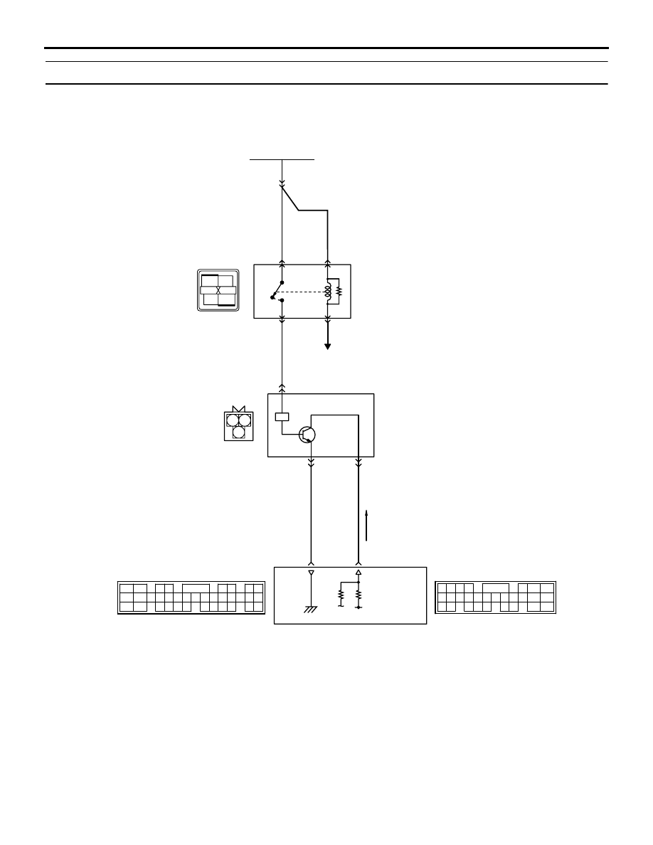
Code No. P0335: Crank Angle Sensor System

OPERATION

• Power is supplied to the crank angle sensor (ter-

minal No. 3) from the engine control relay (termi-
nal No. 4) and is earthed to the engine-ECU 
(terminal No. 34) from the crank angle sensor 
(terminal No. 1).

• A power voltage of 5 V is applied to the crank 

angle sensor output terminal (terminal No. 2) 
from the engine-ECU (terminal No. 43).

1

2

3

4

1 2

3

AK501812

2

3 4

5 6

7 8

9

11 12 13 14 15 16 17 18 19 20

30

21 22 23

24 25

26 27 28 29

3132 33

34 35

1

10

65

43
50

42
49

41
48
60 61

64

46 47
58 59
67 68

45

56
66

52

51

44

53

62

54

63

57

55

5 V

B-12X

Engine control relay

Crank angle sensor

B-117

MU802603

43

1

2

3

Crank angle sensor circuit

34

B

BR-G

R-Y

Battery

Wire colour code
B: Black  LG: Light green  G: Green  L: Blue  W: White  Y: Yellow  SB: Sky blue  BR: Brown  O: Orange  GR: Gray
R: Red  P: Pink  V: Violet  PU: Purple

Engine-ECU

C-121

(MU803783)

C-119

(MU803782)

AB

B-Y

6 <A-13> (*1) or
13 <C-31> (*2)

B-Y

B-Y

NOTE

*1: L.H. drive vehicles
*2: R.H. drive vehicles

2

1

4

3

To engine-ECU

TROUBLESHOOTING

MULTIPORT FUEL INJECTION (MPI)

13A-156

FUNCTION

• The crank angle sensor detects the crank angle 

(position) and inputs a pulse signal to the 
engine-ECU.

• In response to the signal, the engine-ECU con-

trols the injector, etc.

TROUBLE JUDGMENT

Check Condition

• Engine in cranking state.

Judgment Criterion

• The sensor output voltage remains unchanged 

(no pulse signal is inputted) for 2 seconds. 

PROBABLE CAUSES

• Failed crank angle sensor 

• Open/short circuit in crank angle sensor circuit or 

loose connector contact

• Failed engine-ECU

DIAGNOSIS PROCEDURE

STEP 1. M.U.T.-II/III data list

• Refer to Data List Reference Table 

P.13A-372

.

a. Item No. 22: Crank angle sensor 

Q: Is the check result normal? 

YES : 

Intermittent malfunction (Refer to GROUP 

00 

− How to Use 

Troubleshooting/Inspection Service Points 

P.00-5

).

NO : 

Go to Step 2 .

STEP 2. Connector check: B-117 crank angle 
sensor connector

Q: Is the check result normal? 

YES : 

Go to Step 3 .

NO : 

Repair or replace the connector.

AK305020

1

2

3

AB

Connector : B-117

Harness side 
connector

B-117(B)

Crank angle sensor

TROUBLESHOOTING

MULTIPORT FUEL INJECTION (MPI)

13A-157

STEP 3. Perform voltage measurement at B-117 
crank angle sensor connector.

• Disconnect connector, and measure at harness 

side.

• Ignition switch: "ON" 

• Voltage between terminal No. 2 and earth.

OK: 4.9 

 5.1 V

Q: Is the check result normal? 

YES : 

Go to Step 9 .

NO : 

Go to Step 4 .

STEP 4. Perform voltage measurement at C-119 
engine-ECU connector.

• Measure engine-ECU terminal voltage.

• Disconnect B-117 crank angle sensor connector.

• Ignition switch: "ON" 

• Voltage between terminal No. 43 and earth.

OK: 4.9 

 5.1 V

AK305020

1

2

3

AB

Connector : B-117

Harness side 
connector

B-117(B)

Crank angle sensor

AK501994

65

43
50

42
49

41
48
60

61

64

46

47

58

59

67

68

45

56
66

52 51

44

53

62

54

63

57

55

AB

Connector: C-119

C-119 (GR)

C-119 (GR)

Harness side connector

<L. H. drive vehicles>

<R. H. drive vehicles>

AK305020

1

2

3

AB

Connector : B-117

Harness side 
connector

B-117(B)

Crank angle sensor

TROUBLESHOOTING

MULTIPORT FUEL INJECTION (MPI)

13A-158

Q: Is the check result normal? 

YES : 

Go to Step 5 .

NO : 

Go to Step 6 .

STEP 5. Connector check: C-119 engine-ECU 
connector

Q: Is the check result normal? 

YES : 

Check and repair harness between B-117 

(terminal No. 2) crank angle sensor 
connector and C-119 (terminal No. 43) 
engine-ECU connector.

• Check output line for open circuit.

NO : 

Repair or replace the connector.

STEP 6. Connector check: C-119 engine-ECU 
connector

Q: Is the check result normal? 

YES : 

Go to Step 7 .

NO : 

Repair or replace the connector.

AK501994

65

43
50

42
49

41
48
60

61

64

46

47

58

59

67

68

45

56
66

52 51

44

53

62

54

63

57

55

AB

Connector: C-119

C-119 (GR)

C-119 (GR)

Harness side connector

<L. H. drive vehicles>

<R. H. drive vehicles>

AK305020

1

2

3

AB

Connector : B-117

Harness side 
connector

B-117(B)

Crank angle sensor

AK501994

65

43
50

42
49

41
48
60

61

64

46

47

58

59

67

68

45

56
66

52 51

44

53

62

54

63

57

55

AB

Connector: C-119

C-119 (GR)

C-119 (GR)

Harness side connector

<L. H. drive vehicles>

<R. H. drive vehicles>


Content   ..  418  419  420  421   ..