Mitsubishi Lancer Evolution IX. Manual - part 379
 

  Index      Mitsubishi     Mitsubishi Lancer Evolution IX - service repair manual


Search            


Content   ..  377  378  379  380   ..


Mitsubishi Lancer Evolution IX. Manual - part 379


DOOR MIRROR

EXTERIOR

51-29

STEP 2. Connector check: C-214 junction block 
connector

AC304913

21

7

16 15

17

18

20 19

1

2

3

4

5

6

23 22

24

25

28

26

27

9

8

10

11

14

12

13

Connector: C-214

Harness side

AC

Junction block (Front view)

Q: Is the check result normal?

YES : 

Intermittent malfunction (Refer to GROUP 

00 

− How to Cope with Intermittent 

Malfunction 

P.00-5

).

NO : 

Repair the defective connector.

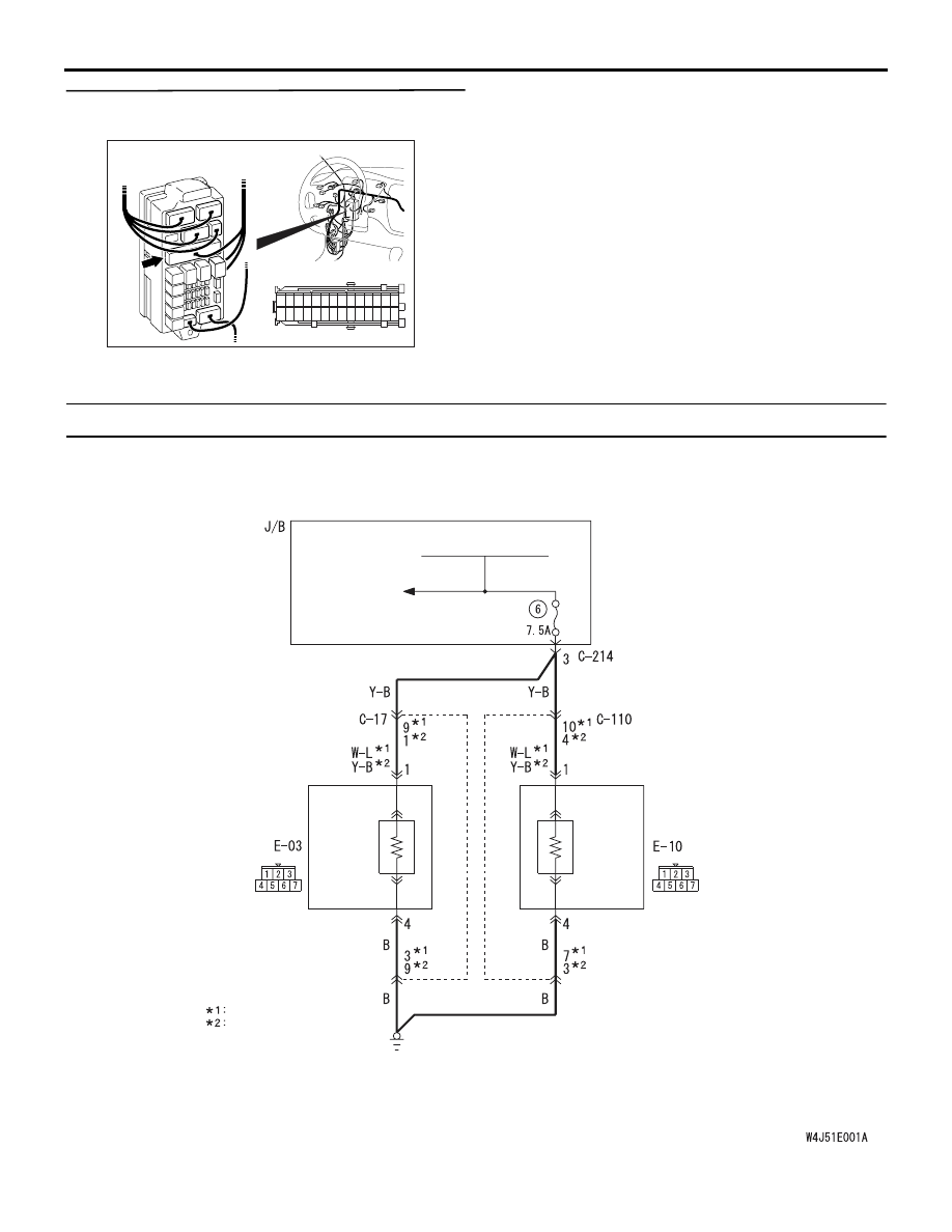
Inspection Procedure 2: Right or Left Heated Door Mirror does not Operate

Wire colour code
B : Black     LG : Light green     G : Green     L : Blue     W : White     Y : Yellow     SB : Sky blue
BR : Brown     O : Orange     GR : Gray     R : Red     P : Pink     V : Violet   

REAR WINDOW 
DEFOGGER RELAY

REAR WINDOW 
DEFOGGER

REMOTE 
CONTROLLED 
MIRROR (RH)

REMOTE 
CONTROLLED 
MIRROR (LH)

MIRROR 
HEATER

MIRROR 
HEATER

NOTE

LH drive vehicles
RH drive vehicles

Heated door mirror circuit

DOOR MIRROR

EXTERIOR

51-30

COMMENTS ON TROUBLE SYMPTOM

If either of the heated door mirrors does not work, the 
door mirror assembly may be defective.

PROBABLE CAUSES

• Malfunction of the door mirror assembly

• Damaged harness wires and connectors

DIAGNOSIS PROCEDURE

STEP 1. Verify the operation of each heated door 
mirror.

Q: Which door mirror does not heat?

Door mirror (RH) : 

Go to Step 2.

Door mirror (LH) : 

Go to Step 9.

STEP 2. Connector check: E-10 door mirror 
assembly (RH) connector

AC304817

Connector: E-10

Harness side

AC

Q: Is the check result normal?

YES : 

Go to Step 3.

NO : 

Repair the defective connector.

STEP 3. Check the door mirror assembly (RH).
Check that the heater element of the door mirror 
assembly (RH) is in good condition (Refer to 

P.51-36

).

Q: Is the check result normal?

YES : 

Go to Step 4.

NO : 

Replace the door mirror assembly (RH).

STEP 4. Resistance measurement at the E-10 
door mirror assembly (RH) connector.

AC304817

Connector: E-10

Harness side

AC

(1) Disconnect the connector, and measure at the 

wiring harness side.

AC304821

Connector E-10

(harness side)

AC

(2) Resistance between E-10 door mirror assembly 

connector terminal No.4 and body earth

OK: 2 

 or less

Q: Is the check result normal?

YES : 

Go to Step 6.

NO : 

Go to Step 5.

DOOR MIRROR

EXTERIOR

51-31

STEP 5. Check the wiring harness between E-10 
door mirror assembly (RH) connector terminal 
No.4 and body earth.

AC304817

Connector: E-10

Harness side

AC

• Check the earth wires for open circuit.

NOTE: 

AC304819

Connector: C-110

AC

Prior to the wiring harness inspection, check interme-
diate connector C-110 and repair if necessary.

Q: Is the check result normal?

YES : 

Intermittent malfunction (Refer to GROUP 

00 

− How to Cope with Intermittent 

Malfunction 

P.00-5

).

NO : 

Repair the wiring harness.

STEP 6. Voltage measurement at the E-10 door 
mirror assembly (RH) connector.
(1) Turn the ignition switch to the ON position.

(2) Rear window defogger switch: ON

AC304817

Connector: E-10

Harness side

AC

(3) Disconnect the connector, and measure at the 

wiring harness side.

AC304826

Connector E-10

(harness side)

AC

(4) Voltage between E-10 door mirror assembly 

connector terminal No.1 and body earth

OK: System voltage

Q: Is the check result normal?

YES : 

Intermittent malfunction (Refer to GROUP 

00 

− How to Cope with Intermittent 

Malfunction 

P.00-5

).

NO : 

Go to Step 7.

STEP 7. Connector check: C-214 junction block 
connector

AC304913

21

7

16 15

17

18

20 19

1

2

3

4

5

6

23 22

24

25

28

26

27

9

8

10

11

14

12

13

Connector: C-214

Harness side

AD

Junction block (Front view)

Q: Is the check result normal?

YES : 

Go to Step 8.

NO : 

Repair the defective connector.

DOOR MIRROR

EXTERIOR

51-32

STEP 8. Check the wiring harness between E-10 
door mirror assembly (RH) connector terminal 
No.1 and C-214 junction block connector 
terminal No.3.

AC304817

Connector: E-10

Harness side

AC

AC304913

21

7

16 15

17

18

20 19

1

2

3

4

5

6

23 22

24

25

28

26

27

9

8

10

11

14

12

13

Connector: C-214

Harness side

AD

Junction block (Front view)

• Check the power supply line for open circuit.

NOTE: 

AC304819

Connector: C-110

AC

Prior to the wiring harness inspection, check interme-
diate connector C-110 and repair if necessary.

Q: Is the check result normal?

YES : 

Intermittent malfunction (Refer to GROUP 

00 

− How to Cope with Intermittent 

Malfunction 

P.00-5

).

NO : 

Repair the wiring harness.

STEP 9. Connector check: E-03 door mirror 
assembly (LH) connector

AC304818

Connector: E-03

Harness side

AC

Q: Is the check result normal?

YES : 

Go to Step 10.

NO : 

Repair the defective connector.

STEP 10. Check the door mirror assembly (LH).
Check that the heater element of the door mirror 
assembly (LH) is in good condition (Refer to 

P.51-36

).

Q: Is the check result normal?

YES : 

Go to Step 11.

NO : 

Replace the door mirror assembly (LH).

STEP 11. Resistance measurement at the E-03 
door mirror assembly (LH) connector.

AC304818

Connector: E-03

Harness side

AC

(1) Disconnect the connector, and measure at the 

wiring harness side.

AC310825

Connector E-03

(harness side)

AB

(2) Resistance between E-03 door mirror assembly 

connector terminal No.4 and body earth

OK: 2 

 or less


Content   ..  377  378  379  380   ..