Mitsubishi Lancer Evolution IX. Manual - part 350
 

  Index      Mitsubishi     Mitsubishi Lancer Evolution IX - service repair manual


Search            


Content   ..  348  349  350  351   ..


Mitsubishi Lancer Evolution IX. Manual - part 350


CHARGING SYSTEM

ENGINE ELECTRICAL

16-17

>>B<< ROTOR INSTALLATION

AK202779

Wire

AB

Remove the brush holding wire after the rotor has 
been installed.

INSPECTION 

M1161001700129

ROTOR

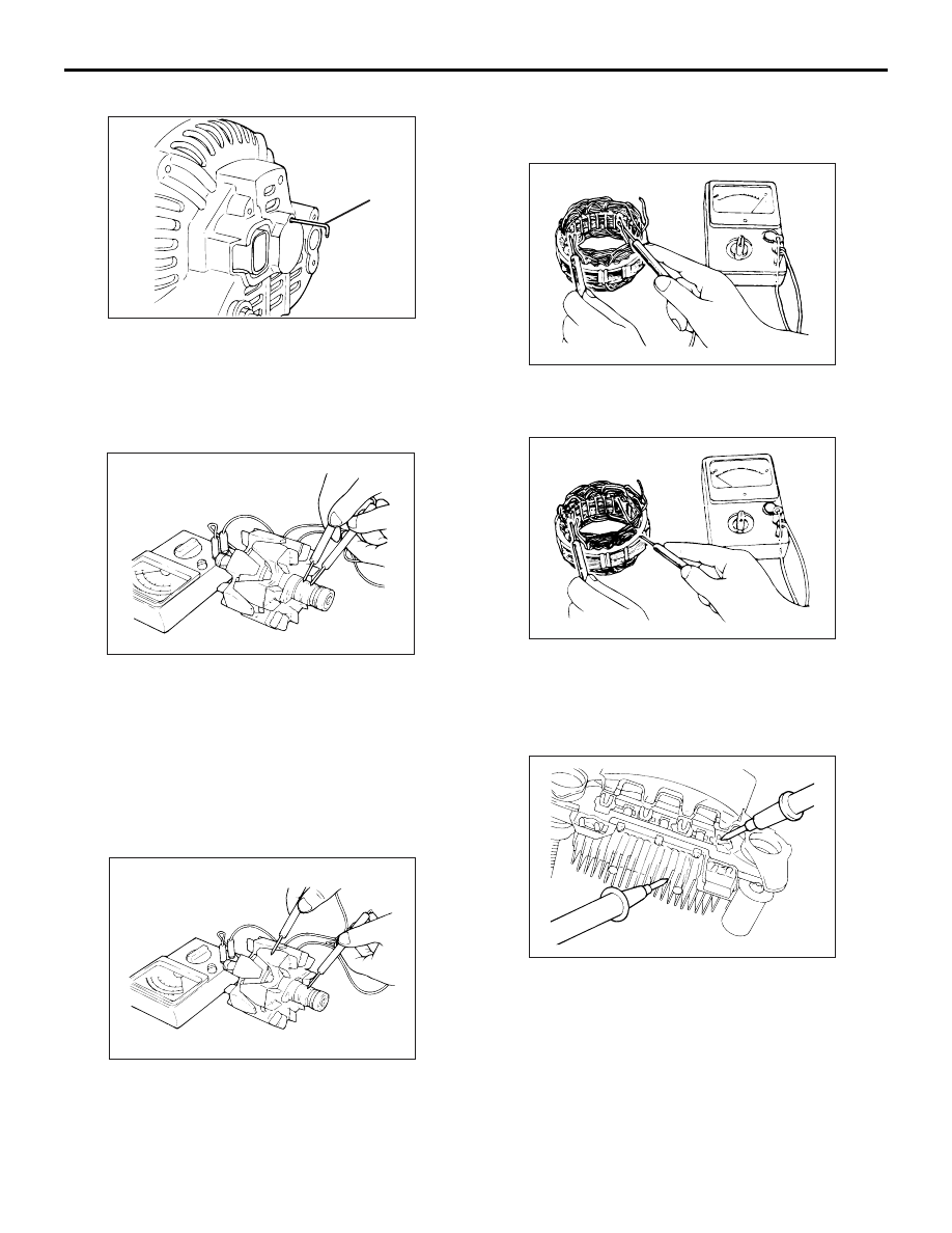
AK202735

1. Measure the resistance between the two slip rings 

of the rotor coil to check the continuity between 
them.
Replace the rotor if the resistance is not within the 
standard value range.

Standard value: 3 

 5 

2. Check the continuity between the slip rings and 

core.

AK202736

3. If continuity is present, replace the rotor.

STATOR

AK202716

1. Check the continuity between coil leads.

If there is no continuity, replace the stator.

AK202717

2. Check the continuity between coil and core.

If there is no continuity, replace the stator.

RECTIFIER ASSEBMLY

AK202803

1. Check the condition of the (+) heat sink by 

checking continuity between the (+) heat sink and 
each of the stator coil lead connecting terminals.
If continuity is present for both terminals, the 
diode is shorted. Replace the rectifier assembly.

AK202802

STARTING SYSTEM

ENGINE ELECTRICAL

16-18

2. Check the condition of the (

−) heat sink by 

checking continuity between the (

−) heat sink and 

each of the stator coil lead connecting terminals.
If continuity is present in both directions, the diode 
is shorted. Replace the rectifier assembly.

AK202804

3. Check the condition of the diode trio by testing 

continuity of each of the three diodes using a 
circuit tester connected to both sides of the diode. 
Connect in a polarity and then reverse the polarity 
for each test.
If continuity exists or no continuity exists for both 
polarities, the diode is defective. Replace the 
rectifier assembly if any of the diodes is defective.

BRUSH

AK202808

Protrusion
length

AB

1. Measure the length of the protrusion of the brush. 

Replace the brush if the protrusion length is 
shorter than the limit.

Limit: 2 mm minimum

2. Unsolder the lead of the brush. The brush will 

come out, becoming ready for removal.

AK202834

Solder

AB

3. Install a new brush by pushing it into the holder as 

shown in the drawing and soldering the lead.

STARTING SYSTEM

GENERAL INFORMATION

M1162000100309

If the ignition switch is turned to the "START" posi-
tion, current flows in the pull-in and holding coils pro-
vided inside magnetic switch, attracting the plunger, 
When the plunger is attracted, the lever connected to 
the plunger is actuated to engage the starter clutch.
On the other hand, attracting the plunger will turn on 
the magnetic switch, allowing the "B" terminal and 
"M" terminal to conduct. Thus, current flows to 
engage the starter motor.

When the ignition switch is returned to the "ON" posi-
tion after starting the engine, the starter clutch is dis-
engaged from the ring gear.
An overrunning clutch is provided between the pinion 
and the armature shaft, to prevent damage to the 
starter.

STARTING SYSTEM

ENGINE ELECTRICAL

16-19

SYSTEM DIAGRAM

AK202970

Pull-in coil

Holding coil

Plunger

Lever

Pinion gear

Overrunning clutch

Yoke

Brush

Armature

Ignition switch

Battery

+

AB

B

M

S

STARTER MOTOR SPECIFICATIONS

Item

Specifications

Type

Reduction drive with planetary gear

Rated output kW/V

1.2/12

No. of pinion teeth

8

SERVICE SPECIFICATIONS

M1162000300080

Item

Standard value

Limit

Pinion gap mm

0.5 

− 2.0

Commutator run-out mm

0.05

0.1

Commutator diameter mm

29.4

28.8

Undercut depth mm

0.5

 0.2

STARTING SYSTEM

ENGINE ELECTRICAL

16-20

STARTER MOTOR ASSEMBLY

REMOVAL AND INSTALLATION

M1162001000781

Pre-removal and Post-installation Operation
• Under Cover Removal and Installation (Refer to GROUP 

51, Front Bumper 

P.51-2

).

• Crossmember Bar Removal and Installation (Refer to 

GROUP 32, Engine Roll Stopper and Centremember 

P.32-7

).

• Front Exhaust Pipe Assembly Removal and Installation 

(Refer to GROUP 15, Exhaust Pipe and Main Muffler 

P.15-13

).

AC210296

3

2

1

AB

4.9 ± 1.0 N·m

30 ± 3 N·m

30 ± 3 N·m

13 ± 2 N·m

4.9 ± 1.0 N·m

Removal steps 

1.

Starter cover

2.

Starter connector and terminal

3.

Starter assembly

STARTER MOTOR ASSEMBLY INSPECTION

M1162001100249

PINION GAP ADJUSTMENT

AKX01239

B

M

S

Battery

Switch

Starter
motor

Wire

AF

1. Disconnect the field coil wire from the M-terminal 

of the magnetic switch.

2. Connect a 12-volt battery between the S-terminal 

and M-terminal.

CAUTION

This test must be performed quickly (in less than 
10 seconds) to prevent the coil from burning.
3. Set the switch to "ON", and the pinion will move 

out.

Removal steps (Continued)


Content   ..  348  349  350  351   ..