Mitsubishi Lancer Evolution IX. Manual - part 344
 

  Index      Mitsubishi     Mitsubishi Lancer Evolution IX - service repair manual


Search            


Content   ..  342  343  344  345   ..


Mitsubishi Lancer Evolution IX. Manual - part 344


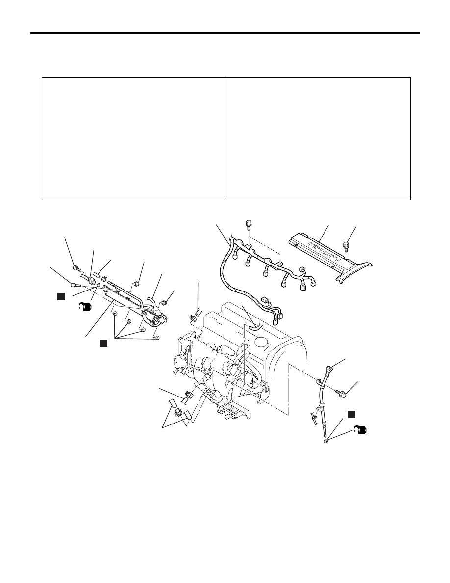
INLET MANIFOLD

INTAKE AND EXHAUST

15-7

INLET MANIFOLD

REMOVAL AND INSTALLATION

M1151003001601

Pre-removal Operation
• Fuel Discharge Prevention (Refer to GROUP 13A, 

On-vehicle Service 

P.13A-398

).

• Under Cover Removal (Refer to GROUP 51, Front 

Bumper 

P.51-2

).

• Engine Coolant Draining (Refer to GROUP 14, On-vehicle 

Service 

P.14-15

).

• Intake Air Duct Removal (Refer to 

P.15-5

).

• Strut Tower Bar Removal (Refer to GROUP 42, Strut 

Tower Bar 

P.42-9

).

• Throttle Body Removal (Refer to GROUP 13A, Throttle 

Body 

P.13A-413

).

• Crossmember Bar Removal (Refer to GROUP 32, Engine 

Roll Stopper, Centremember 

P.32-7

).

• Front Exhaust Pipe Removal (Refer to 

P.15-13

).

Post-installation Operation
• Front Exhaust Pipe Installation (Refer to 

P.15-13

).

• Crossmember Bar Installation (Refer to GROUP 32, 

Engine Roll Stopper, Centremember 

P.32-7

).

• Throttle Body Installation (Refer to GROUP 13A, Throttle 

Body 

P.13A-413

).

• Strut Tower Bar Installation (Refer to GROUP 42, Strut 

Tower Bar 

P.42-9

).

• Intake Air Duct Installation (Refer to 

P.15-5

).

• Engine Coolant Refilling (Refer to GROUP 14, On-vehicle 

Service 

P.14-15

).

• Under Cover Installation (Refer to GROUP 51, Front 

Bumper 

P.51-2

).

• Accelerator Cable Adjustment (Refer to GROUP 17, 

On-vehicle Service 

P.17-2

).

AC310728

3.0 ± 0.5 N·m

1

10

11

N

11 ± 1 N·m

5.0 ± 1.0 N·m

13 ± 1 N·m

(Engine oil)

(Engine oil)

6

5

4

10

7

N

8

N

9

13

14

12

N

AB

4

3

2

Removal steps 

1. Rocker cover centre cover
2. Control wiring harness connection
3. Vacuum hose connection
4. Vacuum hoses connection
5. Fuel return hose connection

>>

A

<< 6. Fuel high-pressure hose connection

>>

A

<< 7. O-ring

<<

A

>>

8. Delivery pipe, fuel injector, fuel return 

pipe and fuel pressure regulator 
assembly

9. Insulators
10. Insulators
11. Oil level gauge and guide assembly
12. O-ring
13. Brake booster vacuum hose 

connection

14. Purge hoses connection

Removal steps (Continued)

AC504960

11 ± 1 N·m

20 ± 2 N·m

36 ± 6 N·m

20 ± 2 N·m

11 ± 1 N·m

11 ± 1 N·m

36 ± 6 N·m

22 ± 4 N·m

24 ± 4 N·m

20 ± 2 N·m

31 ± 3 N·m

11 ± 1 N·m

11 ± 1 N·m

9.0 ± 1.0 N·m

21

23

24

21

25

16

30

22

15

29

18

26

21

20

28

27

31

17

19

N

N

AB

Removal steps 

15. Detonation sensor connector
16. Purge control solenoid valve
17. Vacuum hose
18. Fuel pressure solenoid valve
19. PCV hose

Alternator (Refer to GROUP 16, 
Charging System 

− Alternator 

Assembly 

P.16-12

).

20. EGR solenoid valve connector
21. EGR solenoid valve, vacuum pipe 

and hose assembly

22. Inlet manifold stay
23. EGR valve
24. EGR valve gasket
25. Earth cable connection
26. Harness connection
27. Crank angle sensor connector
28. Harness bracket
29. Alternator brace stay
30. Inlet manifold
31. Inlet manifold gasket

INLET MANIFOLD

INTAKE AND EXHAUST

15-8

Removal steps (Continued)

INLET MANIFOLD

INTAKE AND EXHAUST

15-9

REMOVAL SERVICE POINT
<<A>> DELIVERY PIPE, FUEL INJEC-
TOR, FUEL RETURN PIPE AND FUEL 
PRESSURE REGULATOR ASSEMBLY 
REMOVAL

CAUTION

Be careful not to drop the fuel injector when the 
delivery pipe is removed.
The delivery pipe must be removed with the fuel 
injector, fuel return pipe and fuel pressure regulator 
attached.

INSTALLATION SERVICE POINT
>>A<< O-RING/ FUEL HIGH-PRESSURE 
HOSE INSTALLATION

CAUTION

Do not let the engine oil get into the delivery 
pipe, or it will be damaged.
1. Apply a drop of new engine oil to the O-ring.
2. Turn the fuel high-pressure hose to the right and 

left to install to the delivery pipe.

Be careful not to damage the O-ring. After 
installing, check that the fuel high-pressure hose 
turns smoothly.

3. If the fuel high-pressure hose does not turn 

smoothly, the O-ring may be trapped. Remove the 
fuel high-pressure hose, re-install the fuel 
high-pressure hose into the delivery pipe and 
check again.

4. Tighten the fuel high-pressure hose to the 

specified torque.

Tightening torque: 5.0 

± 1.0 Nm

INSPECTION

M1151003100694

Check the following points; replace the part if a prob-
lem is found.

Inlet Manifold Check

1. Check for damage or cracking of any part.
2. Clogging of the negative pressure (vacuum) outlet 

port, or clogging of the exhaust gas recirculation 
passages.

3. Using a straight edge and feeler gauge, check for 

distortion of the cylinder head installation surface.
Standard value: 0.15 mm or less 
Limit: 0.20 mm

EXHAUST MANIFOLD AND TURBOCHARGER

INTAKE AND EXHAUST

15-10

EXHAUST MANIFOLD AND TURBOCHARGER

REMOVAL AND INSTALLATION

M1151008900060

Pre-removal Operation
• Under Cover Removal (Refer to GROUP 51, Front 

Bumper 

P.51-2

).

• Radiator Removal (Refer to GROUP 14, Radiator 

P.14-24

).

• Air Intake Hose Removal (Refer to 

P.15-5

).

• Air Pipe A, Air Pipe B, Air Pipe C, Air Hose A and Air Hose 

D Removal (Refer to 

P.15-6

).

• Crossmember Bar Removal (Refer to GROUP 32, Engine 

Roll Stopper, Centremember 

P.32-7

).

• Front Exhaust Pipe Removal (Refer to 

P.15-13

).

Post-installation Operation
• Front Exhaust Pipe Installation (Refer to 

P.15-13

).

• Crossmember Bar Installation (Refer to GROUP 32, 

Engine Roll Stopper, Centremember 

P.32-7

).

• Air Pipe A, Air Pipe B, Air Pipe C, Air Hose A and Air Hose 

D Installation (Refer to 

P.15-6

).

• Air Intake Hose installation (Refer to 

P.15-5

).

• Radiator Installation (Refer to GROUP 14, Radiator 

P.14-24

).

• Under Cover Installation (Refer to GROUP 51, Front 

Bumper 

P.51-2

).

AC210648 AB

1

2

3

4

5

6

7

8

9

11

10

23 ± 3 N·m

N

12

8

13

14

15

16

17

18

19

20

21

22

23

24

25

N

N

N

N

N

N

N

N

N

23 ± 3 N·m

14 ± 1 N·m

29 ± 3 N·m

49 ± 5 N·m

49 ± 5 N·m

64 ± 5 N·m

44 ± 5 N·m

59 ± 5 N·m

35 ± 6 N·m

19 ± 1 N·m

9.0 ± 1.0 N·m

14 ± 1 N·m

10 ± 1 N·m

11 ± 1 N·m

42 ± 7 N·m

42 ± 7 N·m

10 ± 1 N·m

17 ± 2 N·m

31 ± 2 N·m

Removal steps 

1. Exhaust manifold cover

<<

A

>> >>

D

<< 2. Oxygen sensor (Front)

3. Turbocharger heat protector
4. Turbocharger water feed pipe 

connection

5. Gaskets
6. Turbocharger water return hose 

connection

<<

B

>>

7. Turbocharger oil feed pipe
8. Gaskets

Removal steps (Continued)


Content   ..  342  343  344  345   ..