Mitsubishi Lancer Evolution IX. Manual - part 343
 

  Index      Mitsubishi     Mitsubishi Lancer Evolution IX - service repair manual


Search            


Content   ..  341  342  343  344   ..


Mitsubishi Lancer Evolution IX. Manual - part 343


ON-VEHICLE SERVICE

INTAKE AND EXHAUST

15-3

1. Disconnect the hose (black) from the vacuum 

terminal, and connect the plug to the hose. 
Connect a pressure gauge to the vacuum terminal 
nipple.

2. Drive at full-throttle acceleration in second gear 

and then measure the supercharging pressure 
when the engine speed in about 3,000 r/min.

Standard value: 96 

 121 kPa

3. If the supercharging pressure deviates from the 

standard value, check the following items for 
possible cause.

• Malfunction of the waste gate actuator

• Leakage of supercharging pressure

• Malfunction of the turbocharger

4. When the indicated supercharging is more than 

standard value, supercharging control may be 
faulty, therefore check the followings.

• Malfunction of the waste gate actuator

• Malfunction of waste gate valve

• Disconnection or cracks of the waste gate actua-

tor rubber hose

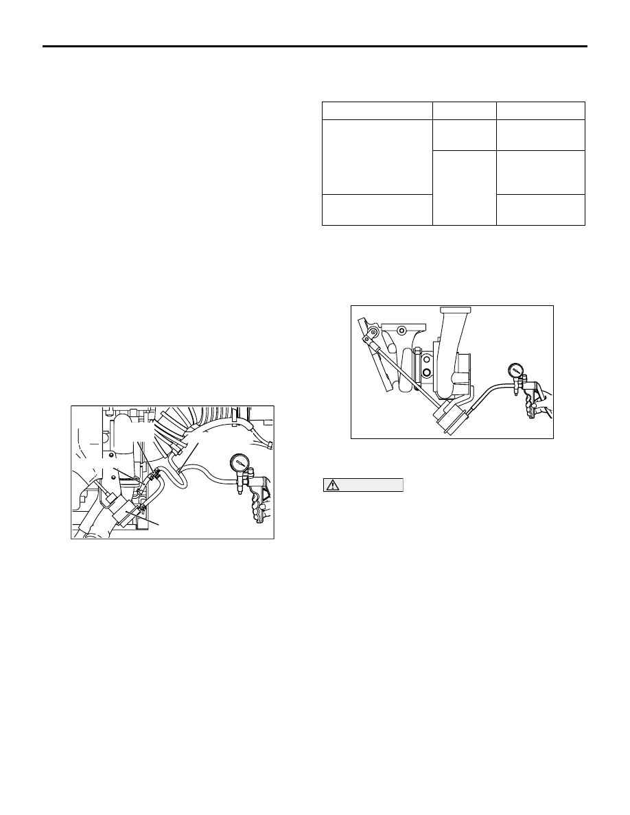
SUPERCHARGING PRESSURE 
CONTROL SYSTEM CHECK

M1151001100160

AK305236

Three-way joint 

Vacuum 
terminal

Boost hose

Waste gate 
actuator

AB

1. Disconnect the hose (black) from the vacuum 

terminal, and connect a three-way joint between 
the hose and the vacuum terminal.

2. Connect a hand vacuum pump to the three-way 

joint.

3. Disconnect the hose from the turbocharger waste 

gate actuator control boost nipple and plug the 
nipple.

4. Applying a negative pressure with the hand 

vacuum pump, check tightness both when the 
hose end is closed and when it is open.

Engine state

Hose end

Normal state

Stop
(Ignition switch: ON)

Opened

Negative 
pressure leaks.

Closed

Negative 
pressure is 
maintained.

Idling (after 
warm-up)

Negative 
pressure leaks.

NOTE: If this check indicates an abnormal condi-
tion, the turbocharger waste gate actuator, turbo-
charger waste gate solenoid or hose is broken.

WASTE GATE ACTUATOR CHECK

M1151001200178

AK200367

1. Connect a manual pump (pressure-application 

type) to nipple.

CAUTION

In order to avoid damage to the diaphragm, do 
not apply a pressure of 117 kPa or higher.
2. While gradually applying pressure, check the 

pressure that begins to activate (approximately 1 
mm stroke) the waste gate actuator rod.

Standard value: Approximately 100 kPa

3. If there is a significant deviation from the standard 

value, check the actuator or the waste gate valve, 
replace actuator or turbocharger assembly if 
necessary.

ON-VEHICLE SERVICE

INTAKE AND EXHAUST

15-4

WASTE GATE SOLENOID VALVE CHECK

M1151001300131

OPERATION CHECK

AK200441

Battery

A

B

AC

1. Connect a hand vacuum pump to the solenoid 

valve nipple A.

2. Using a jumper wire, connect between the 

solenoid valve terminal and battery terminal.

3. Connecting and disconnecting the jumper wire at 

the battery negative terminal to apply a negative 
pressure, check tightness.

Jumper wire B nipple 

condition

Normal condition

Connected

Opened

Negative pressure 
leaks.

Closed

Negative pressure is 
held.

Disconnected Opened

Negative pressure is 
held.

COIL RESISTANCE CHECK

AK200442

Measure the resistance between solenoid valve ter-
minals

Standard value: 29 

 35  (at 20°C)

AIR BY-PASS VALVE CHECK

M1151001600121

AK200443

1. Remove the air bypass valve.
2. Connect the hand vacuum pump to the nipple of 

the air bypass valve.

3. Apply a negative pressure of approximately 54 

kPa, and check that air tightness is maintained.

4. Also check operation of the valve.

Standard value:

Negative pressure

Valve operation

Approximately 59 kPa

It starts opening

INLET MANIFOLD VACUUM CHECK

M1151001800192

Refer to GROUP 11A 

− On-vehicle Service 

P.11A-12

.

AIR CLEANER

INTAKE AND EXHAUST

15-5

AIR CLEANER

REMOVAL AND INSTALLATION

M1151002100594

CAUTION

Parts marked by * are made of recycled-paper mixed plastic material, so observe the following pre-
cautions.

1. Avoid any shock or load to these parts when removing and installing them.
2. Engage the case hinges securely when assembling these parts.

NOTE: Parts marked by * are made of recycled-paper mixed plastic material. Dispose of according to state 
and local laws

AC210412

3

4

5

6*

7

1

8*

9.0 ± 1.0 N·m

4.0 ± 1.0 N·m

AB

2

9

10

11

12

13

4.0 ± 1.0 N·m

4.0 ± 1.0 N·m

9.0 ± 1.0 N·m

9.0 ± 1.0 N·m

9.0 ± 1.0 N·m

9.0 ± 1.0 N·m

N

Removal steps 

1. Intake air duct
2. Battery
3. Air cleaner assembly
4. Airflow sensor assembly
5. Gasket
6. Air cleaner housing cover
7. Air cleaner element

8. Air cleaner housing
9. Air cleaner bracket
10. Waste gate solenoid valve
11. Air pipe C, air by-pass hose and air 

by-pass valve 

12. Vacuum hose connection
13. Air intake hose

Removal steps (Continued)

INTERCOOLER

INTAKE AND EXHAUST

15-6

INTERCOOLER

REMOVAL AND INSTALLATION

M1151002400045

Pre-removal and Post-installation Operation
• Intake Air Duct and Air Cleaner Assembly Removal and 

Installation (Refer to 

P.15-5

).

AC210413

3

4

5

6

7

1

8

6.0 ± 1.0 N·m

2

9

10

11

12

13

12 ± 1 N·m

AB

12 ± 1 N·m

12 ± 1 N·m

12 ± 1 N·m

12 ± 1 N·m

6.0 ± 1.0 N·m

6.0 ± 1.0 N·m

6.0 ± 1.0 N·m

6.0 ± 1.0 N·m

6.0 ± 1.0 N·m

6.0 ± 1.0 N·m

6.0 ± 1.0 N·m

6.0 ± 1.0 N·m

6.0 ± 1.0 N·m

Removal steps 

1.

Vacuum hose connection

2.

Air by-pass valve

3.

Air by-pass hose

4.

Air hose E

5.

Air pipe C

6.

Air hose D

Under cover (Refer to GROUP 51, 
Front Bumper Assembly 

P.51-2

).

7.

Air hose A

Front bumper assembly (Refer to 
GROUP 51, Front Bumper 
Assembly 

P.51-2

).

8.

Air pipe B

9.

Bracket

10. Air hose C
11. Air pipe A
12. Air hose B
13. Intercooler assembly

Removal steps (Continued)


Content   ..  341  342  343  344   ..