Mitsubishi Lancer Evolution IX. Manual - part 330
 

  Index      Mitsubishi     Mitsubishi Lancer Evolution IX - service repair manual


Search            


Content   ..  328  329  330  331   ..


Mitsubishi Lancer Evolution IX. Manual - part 330


ON-VEHICLE SERVICE

ENGINE MECHANICAL

11A-9

CAUTION

• The temperature of the surface of the belt 

should be as close to normal temperature as 
possible.

• Do not allow any contaminants such as water 

or oil to get onto the microphone.

• If strong gusts of wind blow against the 

microphone or if there are any loud sources 
of noise nearby, the values measured by the 
microphone may not correspond to actual 
values.

• If the microphone is touching the belt while 

the measurement is being made, the values 
measured by the microphone may not corre-
spond to actual values.

• Do not take the measurement while the vehi-

cle's engine is running.

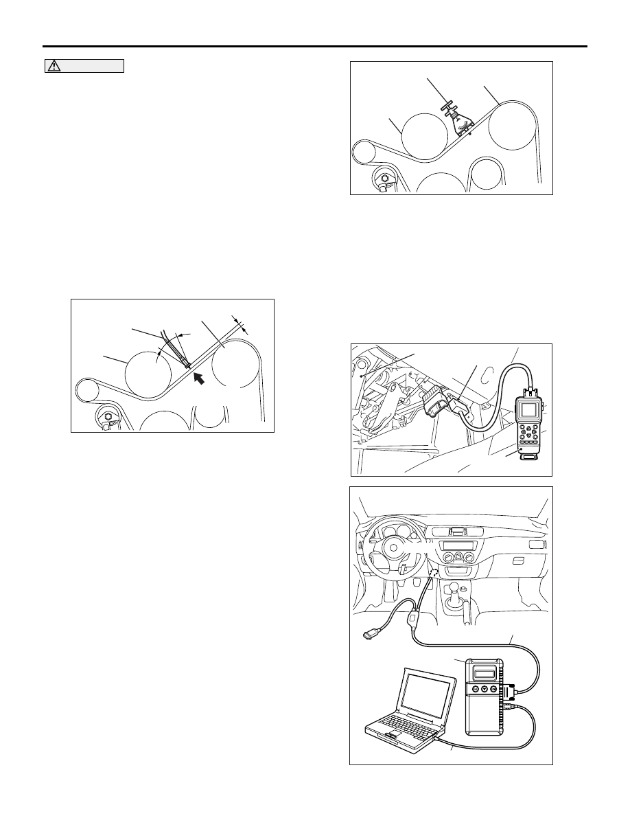
AC102806AB

MB991668

15˚

15˚

Gentry tap with
your finger

Water pump
pulley 

Power steering 
oil pump pulley 

10 – 20 mm

(5) Hold special tool belt tension meter set 

(MB991668) to the middle of the drive belt 
between the pulleys (at the place indicated by 
arrow), approximately 10 

− 20 mm away from 

the rear surface of the belt so that it is 
perpendicular to the belt (within an angle of 

± 

15 degree).

(6) Gently tap the middle of the belt between the 

pulleys (the place indicated by the arrow) with 
your finger as shown in the illustration, and 
measure that the vibration frequency of the 
belt is within the standard value.

Standard value: 110 

 144 Hz

3. If not within the standard value, replace the 

auto-tensioner. (Refer t

P.11A-36

).

When using a tension gauge

1. Check the drive belt tension. (Refer t

P.11A-7

).

AC102807AB

Belt tension gauge

Water pump
pulley

Power steering
oil pump pulley

2. Use a belt tension gauge in the middle of the belt 

between the pulleys (at the place indicated by the 
arrow) to measure that the belt tension is within 
the standard value.

Standard value: 245 

 412 N

3. If not within the standard value, replace the 

auto-tensioner. (Refer to 

P.11A-36

).

IGNITION TIMING CHECK

M1111001701332

AC304777

Steering shaft

AC

MB991502

16-Pin

AC211686

AB

MB991911

16-PIN

MB991827

MB991824 

ON-VEHICLE SERVICE

ENGINE MECHANICAL

11A-10

1. Before inspection, set the vehicle to the 

pre-inspection condition.

2. Turn the ignition switch to the "LOCK" (OFF) 

position and then connect the M.U.T.-II/III to the 
diagnosis connector.

3. Connect a timing light.
4. Start the engine and let it run at idle.
5. Use the M.U.T.-II/III to measure engine idle speed 

and check that it is within the standard value.

Standard value: 800 

± 100 r/min

6. Select No. 17 of the M.U.T.-II/III Actuator test.
7. Check that basic ignition timing is within the 

standard value.

Standard value: 5

° BTDC ± 3°

8. If the basic ignition timing is outside the standard 

value, inspect the MPI system (Refer to GROUP 
13A 

− Troubleshooting − Inspection chart for 

diagnosis code 

P.13A-17

).

CAUTION

If the test is not cancelled, a forced driving will 
continue for 27 minutes. Driving under this con-
dition may damage the engine.
9. Press the M.U.T.-II/III clear key (Select a forced 

driving cancel mode) to release the Actuator test.

10.Check that ignition timing is at the standard value.

Standard value: approximately 5

° BTDC

NOTE: 

.

The ignition timing may fluctuate within 

±

 7

°

This is normal.

In higher altitude, the ignition timing is more 
advanced than the standard value by approxi-
mately 5

°

.

11.Remove the timing light.
12.Turn the ignition switch to the "LOCK" (OFF) 

position and then remove the M.U.T.-II/III.

IDLE SPEED CHECK 

M1111003501215

AC304777

Steering shaft

AC

MB991502

16-Pin

AC211686

AB

MB991911

16-PIN

MB991827

MB991824 

1. Before inspection, set the vehicle to the 

pre-inspection condition.

2. Turn the ignition switch to "LOCK" (OFF) position 

and then connect the M.U.T.-II/III to the diagnosis 
connector.

3. Connect a timing light.
4. Start the engine and let it run at idle.
5. Check that ignition timing is at the standard value.

Standard value: approximately 5

° BTDC

6. Check the idle speed.

Standard value: 800 

± 100 r/min

NOTE: 

.

The idle speed is controlled automatically by 
the idle speed control system.

When using the M.U.T.-II/III, select item No. 22 
and take a reading of the idle speed.

ON-VEHICLE SERVICE

ENGINE MECHANICAL

11A-11

7. If the idle speed is outside the standard value, 

inspect the MPI system (Refer to GROUP 13A 

− 

Troubleshooting 

− Inspection chart for diagnosis 

code 

P.13A-17

).

8. Remove the timing light.
9. Turn the ignition switch to the "LOCK" (OFF) 

position and then remove the M.U.T.-II/III.

IDLE MIXTURE CHECK

M1111002100471

AC304777

Steering shaft

AC

MB991502

16-Pin

AC211686

AB

MB991911

16-PIN

MB991827

MB991824 

1. Before inspection, set the vehicle to the 

pre-inspection condition.

2. Turn the ignition switch to "LOCK" (OFF) position 

and then connect the M.U.T.-II/III to the diagnosis 
connector.

3. Connect a timing light.
4. Start the engine and let it run at idle.
5. Check that ignition timing is at the standard value.

Standard value: approximately 5

° BTDC

6. Run the engine at 2,500 r/min for 2 minutes.

7. Set the CO, HC tester.
8. Check the CO contents and the HC contents at 

idle.

Standard value

CO contents: 0.5 % or less
HC contents: 100 ppm or less

9. If there is a deviation from the standard value, 

check the following items:

• Diagnosis output

• Closed-loop control (when the closed-loop con-

trol is normal, the output signal of the oxygen 
sensor changes between 0 

− 400 mV and 600 − 

1,000 mV at idle.)

• Fuel pressure

• Injector

• Ignition coil, spark plug cable, spark plug

• EGR control system

• Evaporative emission control system

• Compression pressure

NOTE: Replace the three way catalyst when the 
CO and HC contents are not within the standard 
value, even though the result of the inspection is 
normal on all items.

10.Remove the timing light.
11.Turn the ignition switch to the "LOCK" (OFF) 

position and then remove the M.U.T.-II/III.

COMPRESSION PRESSURE CHECK

M1111002601402

AK304215AB

Crank angle
sensor connector

AK304216

Compression gauge

AB

1. Before inspection, set the vehicle to the 

pre-inspection condition.

ON-VEHICLE SERVICE

ENGINE MECHANICAL

11A-12

2. Disconnect the ignition coils and spark plug 

cables.

3. Remove all of the spark plugs.
4. Disconnect the crank angle sensor connector.

NOTE: Doing this will prevent the engine-ECU 
from carrying out ignition and fuel injection.

CAUTION

• Keep away from the spark plug hole when 

cranking.

• If compression is measured with water, oil, 

fuel, etc., that has come from cracks inside 
the cylinder, these materials will become 
heated and will gush out from the spark plug 
hole, which is dangerous.

5. Cover the spark plug hole with a shop towel etc., 

and after the engine has been cranked, check that 
no foreign material is adhering to the shop towel.

6. Set compression gauge to one of the spark plug 

holes.

7. Crank the engine with the throttle valve fully open 

and measure the compression pressure.

Standard value (at engine speed of 250 

r/min):

1,000 kPa

Limit (at engine speed of 250 r/min):

Minimum 640 kPa

8. Measure the compression pressure for all the 

cylinders, and check that the pressure differences 
of the cylinders are below the limit.

Limit: Maximum 98 kPa

9. If there is a cylinder with compression or a 

compression difference that is outside the limit, 
pour a small amount of engine oil through the 
spark plug hole, and repeat the operations in 
steps from 6 to 8.
(1) If the compression increases after oil is added, 

the cause of the malfunction is a worn or 
damaged piston ring and/or cylinder inner 
surface.

(2) If the compression dose not rise after oil is 

added, the cause is a burnt or defective valve 
seat, or pressure is leaking from the gasket.

10.Connect the crank angle sensor connector.
11.Install the spark plugs.
12.Install the ignition coils and spark plug cables.
13.Use the M.U.T.-II/III to erase the diagnosis codes.

NOTE: This will erase the diagnosis code result-
ing from the crank angle sensor connector being 
disconnected.

MANIFOLD VACUUM CHECK

M1111002701034

AC304777

Steering shaft

AC

MB991502

16-Pin

AC211686

AB

MB991911

16-PIN

MB991827

MB991824 

1. Before inspection, set the vehicle to the 

pre-inspection condition.

2. Turn the ignition switch to "LOCK" (OFF) position.
3. Connect the M.U.T.-II/III to the diagnosis 

connector.

AK304217AB

Fuel pressure control
solenoid valve

Vacuum gauge


Content   ..  328  329  330  331   ..