Mitsubishi Lancer Evolution IX. Manual - part 329
 

  Index      Mitsubishi     Mitsubishi Lancer Evolution IX - service repair manual


Search            


Content   ..  327  328  329  330   ..


Mitsubishi Lancer Evolution IX. Manual - part 329


D998713    

SPECIAL TOOLS

ENGINE MECHANICAL

11A-5

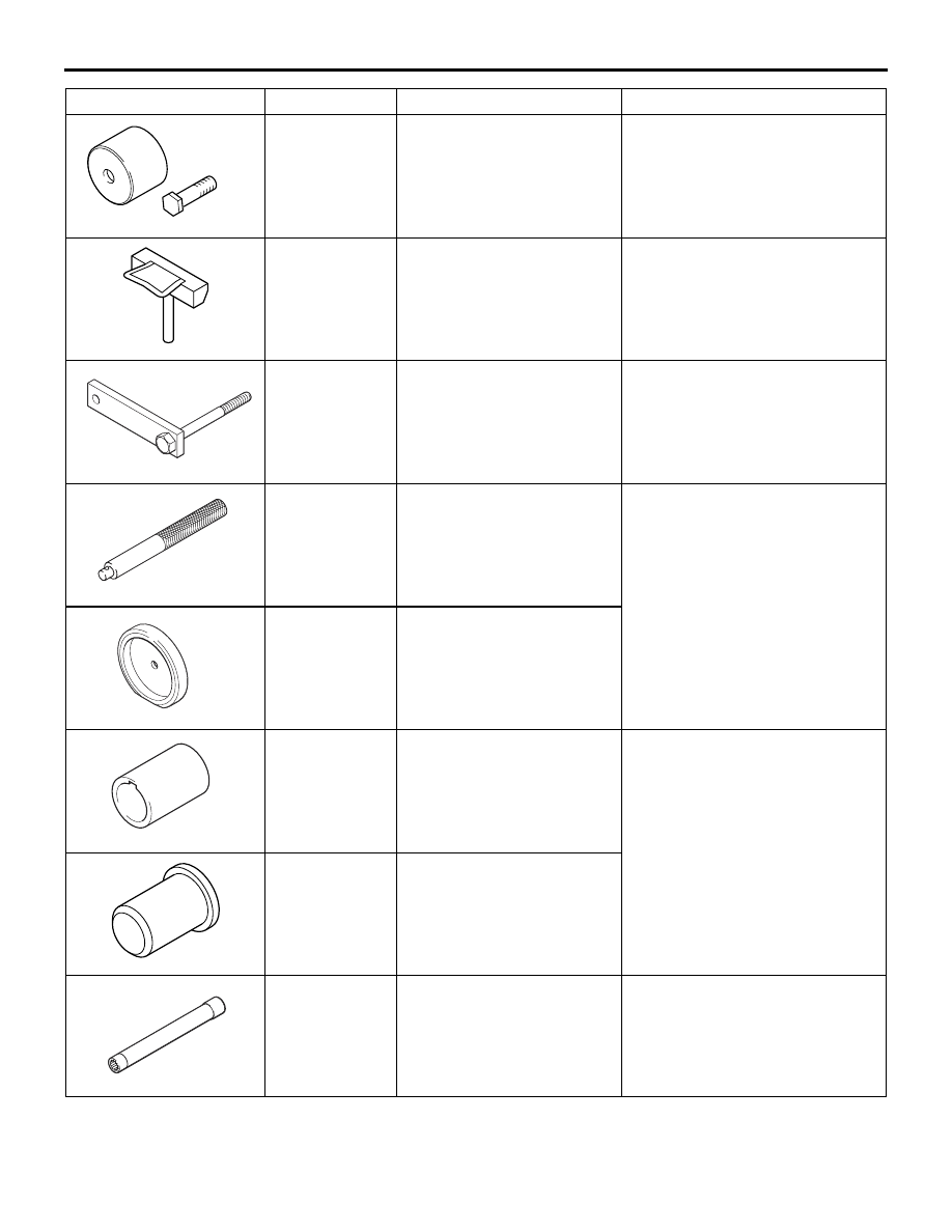
MD998713

Camshaft oil seal installer

Camshaft oil seal installation

D998727

MD998727

Oil pan FIPG cutter

Oil pan removal

D998781  

MD998781

Flywheel stopper

Supporting the flywheel

MB990938

Installer bar

Crankshaft rear oil seal 
installation

D998776

MD998776

Crankshaft rear oil seal 
installer

D998285

MD998285

Crankshaft front oil seal 
guide

Crankshaft front oil seal 
installation 

MD998375

Crankshaft front oil seal 
installer

B991654

MB991654

Cylinder head bolt wrench 
(12)

Removal and installation of 
cylinder head bolt

Tool

Number

Name

Use

D998738

SPECIAL TOOLS

ENGINE MECHANICAL

11A-6

MD998738

Adjusting bolt

Supporting the timing belt 
tensioner arm and timing belt 
tensioner adjuster

B991367

MB991367

Special spanner

Holding the crankshaft camshaft 
drive sprocket

B991385

MB991385

Pin

D998767

MD998767

Tensioner wrench

Valve timing belt tension 
adjustment

B991454

MB991454

Engine hanger balancer

When the engine hanger is used: 
Supporting the engine assembly 
during removal and installation of 
the transmission assembly
NOTE: Special tool MB991454 is 
a part of engine hanger 
attachment set MB991453.

Z203830

MB991895

Engine hanger

B991928

A

B

C

D

E

F

Slide bracket (HI)

MB991928

A: MB991929
B: MB991930
C: MB991931
D: MB991932
E: MB991933
F: MB991934

Engine hanger

A: Joint (50) 

× 2

B: Joint (90) 

× 2

C: Joint (140) 

× 2

D: Foot (standard) 

× 4

E: Foot (short) 

× 2

F: Chain and hook 

assembly

Tool

Number

Name

Use

ON-VEHICLE SERVICE

ENGINE MECHANICAL

11A-7

ON-VEHICLE SERVICE

DRIVE BELT TENSION CHECK

M1111003100612

CAUTION

Check the drive belt tension after turning the 
crankshaft clockwise one turn or more.

AC211616AB

A

Indicator mark

1. Make sure that the indicator mark is within the 

area marked with A in the illustration.

2. If the mark is out of the area, replace the drive 

belt. (Refer to 

P.11A-15

).

NOTE: The drive belt tension check is not neces-
sary as auto-tensioner is adopted.

AUTO-TENSIONER CHECK

M1111003000284

OPERATION CHECK

1. Turn OFF the engine from the idle state then 

check to see that the drive belt is not protruding 
from the pulley width of the auto-tensioner.

2. Remove the drive belt.(Refer to 

P.11A-15

).

Y1848AU

AC211619

3. Securely insert the spindle handle or ratchet 

handle with a 12.7 mm insertion angle into the jig 
hole of the auto tensioner. Turn the auto-tensioner 
to the left and right to check and see that there is 
no threading.

4. If there are any problems in the procedure 1 or 3, 

replace the auto-tensioner.(Refer to 

P.11A-36

).

5. Install the drive belt.(Refer to 

P.11A-15

).

FUNCTION CHECK

You can verify if the auto-tensioner is defective or not 
by checking the drive belt tension.

When using the M.U.T.-II

1. Check the drive belt tension. (Refer t

P.11A-7

).

2. Measure the drive belt tension vibration frequency 

by the following procedures:

AC211432

16-pin

AB

M.U.T.-II

MB991668

CAUTION

To prevent damage to the M.U.T.-II, always turn 
the ignition switch to the "LOCK" (OFF) position 
before connecting or disconnecting the M.U.T.-II.

(1) Connect special tool belt tension meter set 

(MB991668) to the M.U.T.-II.

(2) Connect the M.U.T.-II to the diagnosis 

connector.

(3) Turn the ignition switch to "ON" position, and 

select "BELT TENSION" on the menu screen.

ON-VEHICLE SERVICE

ENGINE MECHANICAL

11A-8

CAUTION

• The temperature of the surface of the belt 

should be as close to normal temperature as 
possible.

• Do not allow any contaminants such as water 

or oil to get onto the microphone.

• If strong gusts of wind blow against the 

microphone or if there are any loud sources 
of noise nearby, the values measured by the 
microphone may not correspond to actual 
values.

• If the microphone is touching the belt while 

the measurement is being made, the values 
measured by the microphone may not corre-
spond to actual values.

• Do not take the measurement while the vehi-

cle's engine is running.

AC102806AB

MB991668

15˚

15˚

Gentry tap with
your finger

Water pump
pulley 

Power steering 
oil pump pulley 

10 – 20 mm

(4) Hold special tool belt tension meter set 

(MB991668) to the middle of the drive belt 
between the pulleys (at the place indicated by 
arrow), approximately 10 

− 20 mm away from 

the rear surface of the belt so that it is 
perpendicular to the belt (within an angle of 

± 

15 degree).

(5) Gently tap the middle of the belt between the 

pulleys (the place indicated by the arrow) with 
your finger as shown in the illustration, and 
measure that the vibration frequency of the 
belt is within the standard value.

Standard value: 110 

 144 Hz

3. If not within the standard value, replace the 

auto-tensioner. (Refer to 

P.11A-36

).

When using the V.C.I.

1. Check the drive belt tension. (Refer t

P.11A-7

).

2. Measure the drive belt tension vibration frequency 

by the following procedures:

AC211433

16-pin

AB

MB991824

MB991668

MB991911

CAUTION

To prevent damage to special tool V.C.I. 
(MB991824), always turn the ignition switch to 
the "LOCK" (OFF) position before connecting or 
disconnecting special tool V.C.I. (MB991824).

(1) Connect special tool belt tension meter set 

(MB991668) to special tool V.C.I. (MB991824).

(2) Connect special tool M.U.T.-III main harness B 

(MB991911) to special tool V.C.I. (MB991824).

(3) Connect special tool M.U.T.-III main harness B 

(MB991911) to the diagnosis connector.

(4) Turn the ignition switch to "ON" position, and 

select "Belt Tension" on the menu screen.


Content   ..  327  328  329  330   ..