Mitsubishi Lancer Evolution IX. Manual - part 305
 

  Index      Mitsubishi     Mitsubishi Lancer Evolution IX - service repair manual


Search            


Content   ..  303  304  305  306   ..


Mitsubishi Lancer Evolution IX. Manual - part 305


DRIVESHAFT ASSEMBLY

FRONT AXLE

26-13

CAUTION

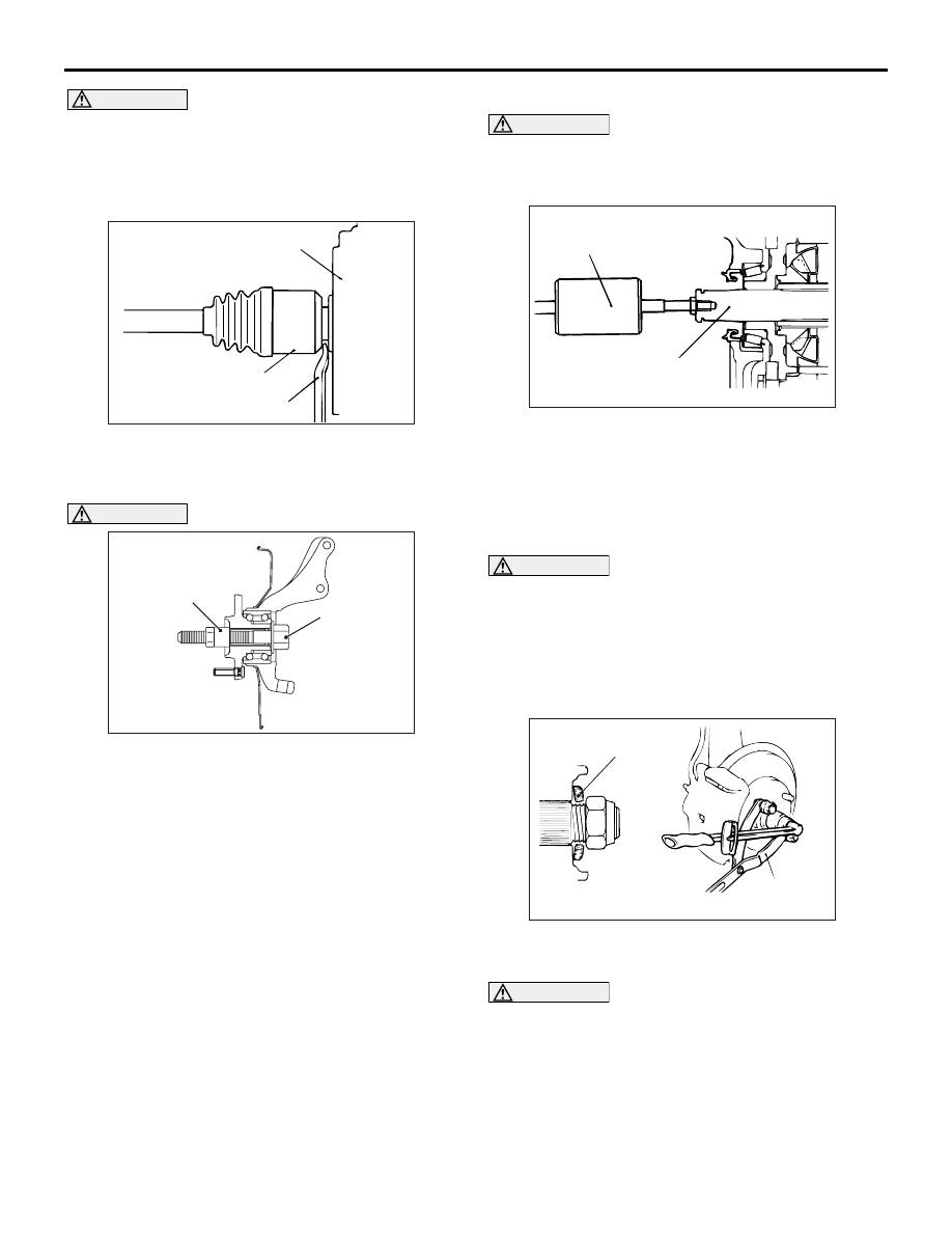
• Do not pull on the driveshaft; doing so will 

damage the TJ; be sure to use the pry bar.

AC100141

Transmission

TJ assembly

Pry bar

AG

When pulling the driveshaft out from the 
transmission, be careful that the spline part of 
the driveshaft does not damage the oil seal.

3. Insert a pry bar between the transmission case 

and the driveshaft, and then pry and remove the 
driveshaft from the transmission.

AC210315

MB991017

MB991000

AF

CAUTION

Do not apply pressure to the wheel bearing by 
the vehicle weight to avoid possible damage 
when the driveshaft is removed. If, however, vehi-
cle weight must be applied to the bearing in mov-
ing the vehicle, temporarily secure the wheel 
bearing by using the following special tools. 

• Spacer (MB991000)
• Front hub remover and installer (MB991017)

<<D>>OUTPUT SHAFT REMOVAL

CAUTION

When pulling the output shaft out from the 
tansaxle, be careful that the spline part of the 
output shaft does not damage the oil seal.

AC102556

MB991721

Output shaft

AC

Use special tool slide hammer (MB991721) to 
remove the output shaft.

INSTALLATION SERVICE POINTS
>>A<< OUTPUT SHAFT/DRIVESHAFT 
INSTALLATION

CAUTION

When installing the output shaft or the driveshaft, 
be careful that the spline part of the output shaft 
or the driveshaft do not damage the oil seal.

>>B<< WASHER/DRIVESHAFT NUT 
INSTALLATION

AC102465AD

MB990767

Washer

1. Be sure to install the driveshaft washer in the 

specified direction.

CAUTION

Before securely tightening the driveshaft nuts, 
make sure there is no load on the wheel bear-
ings. Otherwise the wheel bearing will be dam-
aged.
2. Using special tool front hub and end yoke holder 

(MB990767), tighten the driveshaft nut to the 
specified torque.

Tightening torque: 226 

± 29 N

DRIVESHAFT ASSEMBLY

FRONT AXLE

26-14

DISASSEMBLY AND REASSEMBLY

M1261003700586

CAUTION

• Be careful not to damage the ABS rotor, which is attached to the EBJ outer race during disassem-

bly and reassembly.

AC211633

3

4

6

1

2

4

1

2

9

1

2

4

8

5

6

2

1

4

8

10

9

7

6

5

3

N

N

N

AC

EBJ boot repair kit

TJ boot repair kit

TJ repair kit

Grease 
for TJ

Grease 
for EBJ

10

Disassembly steps 

>>

D

<<

1.

TJ boot band (large)

>>

D

<<

2.

TJ boot band (small)

<<

A

>>

>>

C

<<

3.

TJ case

4.

Snap ring

<<

A

>>

>>

B

<<

5.

Spider assembly

<<

B

>>

>>

A

<<

6.

TJ boot

7.

EBJ assembly

8.

EBJ boot band (small)

9.

EBJ boot band (large)

10. EBJ boot

Never disassemble the EBJ assembly except when replacing the EBJ boot.

TJ: Tripod Joint
EBJ:Eight Ball Fixed Joint

Disassembly steps (Continued)

DRIVESHAFT ASSEMBLY

FRONT AXLE

26-15

LUBRICATION POINTS

AC211634

5

AC

CAUTION

CAUTION

Grease: repair kit grease
Amount used: 100 – 10 g 

Grease: repair kit grease
Amount used: 145 – 10 g 

The driveshaft joint uses special 
grease. Do not mix old and new or
different types of grease.

The driveshaft joint uses special 
grease. Do not mix old and new or
different types of grease.

DRIVESHAFT ASSEMBLY

FRONT AXLE

26-16

DISASSEMBLY SERVICE POINTS
<<A>> TJ CASE/SPIDER ASSEMBLY 
REMOVAL

CAUTION

Do not disassemble the spider assembly.
1. Wipe off grease from the spider assembly and the 

inside of the TJ case.

2. Always clean the spider assembly when the 

grease contains water or foreign material.

<<B>> TJ BOOT REMOVAL 

1. Wipe off grease from the shaft spline.
2. When reusing the TJ boot, wrap plastic tape 

around the shaft spline to avoid damaging the 
boot.

REASSEMBLY SERVICE POINTS
>>A<< TJ BOOT INSTALLATION

Wrap plastic tape around the shaft spline, and then 
install the TJ boot band (small) and TJ boot.

>>B<< SPIDER ASSEMBLY 
INSTALLATION

CAUTION

• The driveshaft joint use special grease. Do 

not mix old and new or different types of 
grease.

• If the spider assembly has been cleaned, take 

special care to apply the specified grease.

1. Apply the specified grease furnished in the repair 

kit to the spider assembly between the spider axle 
and the roller.

Specified grease: Repair kit grease

AC102654AC

Chamfered
side

2. Install the spider assembly to the shaft from the 

direction of the spline chamfered side.

>>C<< TJ CASE INSTALLATION

CAUTION

The driveshaft joint use special grease. Do not 
mix old and new or different types of grease.

AC102656 AC

After applying the specified grease to the TJ case, 
insert the driveshaft and apply grease one more 
time.

Specified grease: Repair kit grease
Amount to use: 145 

±  10 g

NOTE: The grease in the repair kit should be divided 
in half for use, respectively, at the joint and inside the 
boot.

>>D<< TJ BOOT BAND (SMALL)/TJ BOOT 
BAND (LARGE) INSTALLATION

AC102657

A

AC

Set the TJ boot bands at the specified distance in 
order to adjust the amount of air inside the TJ boot, 
and then tighten the TJ boot band (small), TJ boot 
band (large) securely.

Standard value (A): 85 

± 3 mm

INSPECTION

M1261003800215

• Check the driveshaft for damage, bending or cor-

rosion.

• Check the driveshaft spline part for wear or dam-

age.

• Check the spider assembly for roller rotation, 

wear or corrosion.

• Check the groove inside TJ case for wear or cor-

rosion.


Content   ..  303  304  305  306   ..