Mitsubishi Lancer Evolution IX. Manual - part 304
 

  Index      Mitsubishi     Mitsubishi Lancer Evolution IX - service repair manual


Search            


Content   ..  302  303  304  305   ..


Mitsubishi Lancer Evolution IX. Manual - part 304


FRONT AXLE HUB ASSEMBLY

FRONT AXLE

26-9

<<E>> DRIVESHAFT REMOVAL

AC201827

MB991354

MB990244
(Three)

MB990242

MB990767

AE

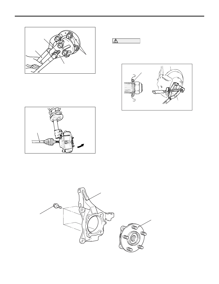
1. Use the following special tools to push out the 

driveshaft from the hub and knuckle.

• Puller shaft (MB990242)

• Puller bar (MB990244)

• Puller body (MB991354)

AC102551AC

Driveshaft

Front hub and end yoke holder (MB990767)

2. Withdraw the driveshaft from the hub by pulling 

the bottom of the hub and knuckle towards you.

3. Hang the driveshaft on the vehicle body with a 

rope.

INSTALLATION SERVICE POINT
>>A<< WASHER/ DRIVESHAFT NUT 
INSTALLATION

CAUTION

Before securely tightening the driveshaft nuts, 
make sure there is no load on the wheel bear-
ings. Otherwise the wheel bearings will be dam-
aged.

AC102465AD

MB990767

Washer

1. Be sure to install the driveshaft washer in the 

specified direction.

2. Using special tool front hub and end yoke holder 

(MB990767), tighten the driveshaft nut to the 
specified torque.

Tightening torque: 226 

± 29 N

INSPECTION

M1261001800286

• Check the hub for cracks and spline for wear.

• Check the knuckle for cracks.

DISASSEMBLY AND REASSEMBLY

M1261001900261

AC211631AC

1

88 ± 10 N·m

2

Disassembly steps 

1.

Knuckle

<<

A

>>

2.

Front wheel hub assembly

FRONT AXLE HUB ASSEMBLY

FRONT AXLE

26-10

DISASSEMBLY SERVICE POINTS
<<A>> FRONT WHEEL HUB ASSEMBLY 
REMOVAL

1. If the front wheel hub is seized, remove the 

knuckle together with front wheel hub and fix them 
with a vise.

AC210309AE

MB990211

MB991354

MB990244

2. Use the following special tools to pull out the front 

wheel hub from the knuckle.

• Puller bar (MB990244)

• Puller body (MB991354)

• Slide hammer (MB990211)

INSPECTION

M1261002000108

WHEEL BEARING ROTATION STARTING 
TORQUE AND AXIAL PLAY CHECK

AC301927AF

MB991000

MB991017

1. Tighten the following special tools to the specified 

torque.

• Front hub remover and installer (MB991017)

• Spacer (MB991000)

Tightening torque: 226 

± 29 Nm

2. Hold the front wheel hub assembly in a vice with a 

wooden block.

3. Rotate the hub in order to seat the bearing.

AC206090 AD

MB990326 Wooden

block

MB990685

Wooden
block

4. Measure the wheel bearing rotation starting 

torque by using the following special tools.

• Preload socket (MB990326)

• Torque wrench (MB990685)

Limit: 1.03 N

m

5. If the rotation starting torque is not within the limit 

range while the nut is tightened to 226 

± 29 N⋅m, 

replace the front wheel hub assembly. If there are 
any signs of binding or tight spots when the wheel 
bearing turns, replace it.

AC206091AG

Wooden
block

Wooden
block

MB991017

6. Measure to determine whether the wheel bearing 

axial play is within the specified limit or not.

Limit: 0.05 mm

7. If the play is not within the limit range while the nut 

is tightened to 226 

± 29 N⋅m, replace the front 

wheel hub assembly.

DRIVESHAFT ASSEMBLY

FRONT AXLE

26-11

DRIVESHAFT ASSEMBLY

REMOVAL AND INSTALLATION

M1261003500850

CAUTION

• Do not strike the ABS rotors installed to the EBJ outer race of driveshaft against other parts when 

removing or installing the driveshaft. Otherwise the ABS rotors will be damaged.

• Be careful not to strike the pole piece at the tip of the front ABS sensor with tools during servicing 

work.

Pre-installation Operation

• Front under cover, side under cover removal

• Transmission Fluid Draining (Refer to GROUP 

22A, On-vehicle service 

− Transmission oil 

replacement 

P.22A-152

).

• Transfer Oil Draining (Refer to GROUP 22A, 

On-vehicle service 

− Transfer oil 

P.22A-152

).

Post-installation Operation

• Check the ball Joint dust cover for cracks or 

damage by pushing it with your finger.

• Transfer Oil Filling (Refer to GROUP 22A, 

On-vehicle service 

− Transfer oil 

P.22A-152

).

• Transmission Fluid Filling (Refer to GROUP 

22A, On-vehicle service 

− Transmission oil 

replacement 

P.22A-152

).

• Front Under cover, side under cover Installation

AC211632

N

11

12

12

N

8

6

5

3

4

N

1

25 ± 5 N·m

226 ± 29 N·m

108 ± 10 N·m

N

9

AC

2

39 ± 5 N·m

7

10

39 ± 5 N·m

Removal steps 

1.

Split pin

<<

A

>>

>>

B

<<

2.

Driveshaft nut

>>

B

<<

3.

Washer

4.

Front ABS sensor

5.

Front ABS sensor harness bracket

6.

Brake hose bracket

7.

Stabilizer bar link connection

8.

Lower arm ball joint connection

<<

B

>>

9.

Self-locking nut (tie rod end 
connection)

<<

C

>>

>>

A

<<

10. Driveshaft

<<

D

>>

>>

A

<<

11. Output shaft
12. Circlip

During maintenance, take care not to contact the parts or tools to the caliper because the paint of 
caliper will be scratched. And if there is brake fluid on the caliper, wipe off quickly.

Removal steps (Continued)

DRIVESHAFT ASSEMBLY

FRONT AXLE

26-12

REMOVAL SERVICE POINTS
<<A>> DRIVESHAFT NUT REMOVAL

CAUTION

Do not apply pressure to the wheel bearing by 
the vehicle weight to avoid possible damage 
when the driveshaft nut is loosened.

AC102462

AC

MB990767

Use special tool front hub and end yoke holder 
(MB990767) to fix the hub and remove the driveshaft 
nut.

<<B>> SELF-LOCKING NUT (TIE ROD 
END CONNECTION) REMOVAL

CAUTION

• Do not remove the nut from ball joint. Loosen 

it and use special tool to avoid possible dam-
age to ball joint threads.

AC208247AJ

Cord

Bolt

MB991897
or
MB992011

Nut

Ball joint

Hang special tool with cord to prevent it from 
falling. 

1. Install special tool ball joint remover (MB991897 

or MB992011) as shown in the figure.

AC106821

Knob

Parallel

Bolt

Correct

Wrong

AD

2. Turn the bolt and knob as necessary to make the 

jaws of special tool parallel, tighten the bolt by 
hand and confirm that the jaws are still parallel.
NOTE: When adjusting the jaws in parallel, make 
sure the knob is in the position shown in the fig-
ure.

3. Tighten the bolt with a wrench to disconnect the 

tie rod end.

<<C>> DRIVESHAFT REMOVAL

AC102550

MB990244
(Three)

MB991354

MB990242

MB990767

AC

1. Use the following special tools to push out the 

driveshaft from the hub.

• Puller shaft (MB990242)

• Puller bar (MB990244)

• Puller body (MB991354)

AC102551AC

Drive shaft

Front hub and end yoke holder (MB990767)

2. Remove the driveshaft from the hub by pulling the 

bottom of the brake disc towards you.


Content   ..  302  303  304  305   ..