Mitsubishi Lancer Evolution IX. Manual - part 273
 

  Index      Mitsubishi     Mitsubishi Lancer Evolution IX - service repair manual


Search            


Content   ..  271  272  273  274   ..


Mitsubishi Lancer Evolution IX. Manual - part 273


IGNITION SWITCH

CHASSIS ELECTRICAL

54A-29

IGNITION SWITCH

REMOVAL AND INSTALLATION

M1543002101084

WARNING

Before removal of the air bag module, refer to GROUP 52B, SRS Service Precautions and 
Air Bag Module and Clock Spring 

P.52B-3

.

AC310331

2

3

4

6

7

1

5

AB

8

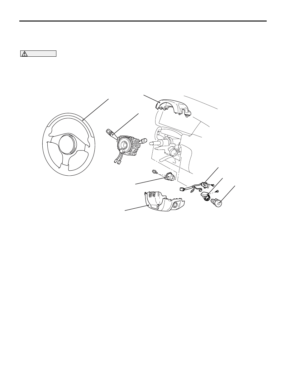
Removal steps 

1. Column cover lower
2. Column cover upper
3. Steering wheel and air bag module 

assembly (Refer to GROUP 37, 
Steering wheel 

P.37-13

).

4. Clock spring and column switch 

assembly (Refer to GROUP 52B, 
Driver’s, Front Passenger’s Air Bag 
Modules and Clock Spring 

P.52B-110

).

<<

A

>>

5. Steering lock cylinder

Ignition switch connector

6. Ignition switch
7. Immobilizer-ECU

Key reminder switch connector

8. Key reminder switch and bulb 

assembly

When removing and installing the steering wheel, do not let it bump against the air bag 
module.

Removal steps (Continued)

IGNITION SWITCH

CHASSIS ELECTRICAL

54A-30

REMOVAL SERVICE POINT
<<A>> STEERING LOCK CYLINDER 
REMOVAL

AC304831AB

Locking pin

1. Insert the key in the steering lock cylinder and turn 

it to the "ACC" position.

2. Using a small Phillips head screwdriver, pull the 

steering lock cylinder toward you.

INSPECTION

M1544009700270

IGNITION SWITCH CONTINUITY CHECK

AC304833AB

Disconnect ignition switch connector C-208 without 
removing the ignition switch. Then check the continu-
ity.

Switch 
position 

Tester 
connection

Specified 
condition

"LOCK" (OFF)

− 2, 1 − 3, 1 − 

4, 1

− 5, 1 − 6, 2 

− 3, 2 − 4, 2− 5, 

− 6, 3 − 4, 3− 

5, 3 

− 6, 4− 5, 4 

− 6, 5 − 6

Open circuit

"ACC"

− 6

Less than 2 
ohms

"ON"

− 2, 1 − 4, 1 − 

6, 2 

− 4, 2 − 6, 4 

− 6

Less than 2 
ohms

"START"

− 2, 1 − 5, 2 − 

5

Less than 2 
ohms

KEY REMINDER SWITCH CONTINUITY 
CHECK

AC304834AB

Disconnect key reminder switch connector C-207 
without removing the ignition switch and key 
reminder switch. Then check the continuity.

Status of 
ignition key

Tester 
connection

Specified 
condition

Removed

− 6

Less than 2 
ohms

Inserted

− 6

Open circuit

COMBINATION METER ASSEMBLY

CHASSIS ELECTRICAL

54A-31

COMBINATION METER ASSEMBLY

SERVICE SPECIFICATIONS

M1543000300432

Item

Standard value

Speedometer indication tolerance km/h

20

20 

− 24

40

40 

− 44

80

80 

− 85

120

121 

− 127

160

162 

− 169

200

203 

− 211

Tachometer indication tolerance r/min

700

± 120 

2,000

− 175 + 225

3,000

− 175 + 300

4,000

− 225 + 375

5,000

− 225 + 425

6,000

− 225 + 475

7,000

− 200 + 500

8,000

− 100 + 500

Fuel tank gauge unit (main) resistance 

Float position F (highest)

± 1

Float position E (lowest)

36.4 

± 1

Fuel tank gauge unit (sub) resistance 

Float position F (highest)

± 1

Float position E (lowest)

73.6 

± 1

Fuel gauge unit (main) float height mm

Float position F (A)

33.3 

± 2.0

Float position E (B)

121.9 

± 2.0

Fuel gauge unit (sub) float height mm

Float position F (A)

5.7 

± 2.0

Float position E (B)

141.0 

± 2.0

Engine coolant temperature gauge unit resistance 

104 + 13.5 (at 70

°C)

Combination meter internal resistance 

Engine coolant 
temperature gauge to earth 
(terminal No. 1 

− 21)

233 

± 3

Fuel gauge to earth 
(terminal No. 31 

− 51)

181 

± 2

SEALANT

M1543024600028

Item

Specified sealant

Engine coolant temperature gauge unit

3M 1215 or equivalent

COMBINATION METER ASSEMBLY

CHASSIS ELECTRICAL

54A-32

SPECIAL TOOLS

M1543000603045

Tool

 Number

Name

Use

MB990784

MB990784

Ornament remover

Removal of meter bezel and 
Instrument panel ornament

B991502

MB991502

M.U.T.-II sub assembly Reading MPI system 

diagnosis code

MB991910

MB991826

MB991955

MB991911

MB991824

MB991827

MB991825

A

B

C

D

E

F

DO NOT USE

MB991955
A: MB991824
B: MB991827
C: MB991910
D: MB991911
E: MB991825
F: MB991826

M.U.T.-III sub-assembly
A: Vehicle 
Communication 
Interface (V. C. I.)
B: M.U.T.-III USB cable
C: M.U.T.-III Main 
harness A (Vehicles 
with CAN 
communication system)
D: M.U.T.-III Main 
harness B (Vehicles 
without CAN 
communication system)
E: M.U.T.-III 
Measurement adapter
F: M.U.T.-III Trigger 
harness

Reading MPI system 
diagnosis code

CAUTION

M.U.T.-III main harness B 
(MB991911) should be 
used. M.U.T.-III main 
harness A should not be 
used for this vehicle.


Content   ..  271  272  273  274   ..