Mitsubishi Lancer Evolution IX. Manual - part 252
 

  Index      Mitsubishi     Mitsubishi Lancer Evolution IX - service repair manual


Search            


Content   ..  250  251  252  253   ..


Mitsubishi Lancer Evolution IX. Manual - part 252


INPUT SIGNAL PROCEDURES

SMART WIRING SYSTEM (SWS) USING SWS MONITOR

54C-267

Step 6. SWS monitor data list.

<Selected item> ETACS ECU

• Driver's door: open

OK: Normal condition is displayed.

Q: Is the check result normal?

YES : 

The trouble can be an intermittent 

malfunction (Refer to GROUP 00 

− How to 

Cope with Intermittent Malfunction 

P.00-5

).

NO : 

Replace the ETACS-ECU.

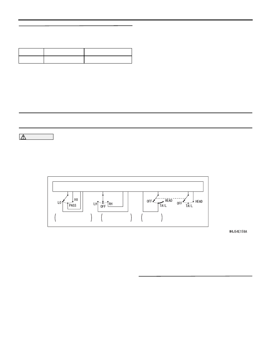
INSPECTION PROCEDURE L-4: The column switch (lighting, turn-signal lamp and headlamp washer 
switch) signal is not received.

CAUTION

Whenever the ECU is replaced, ensure that the 
input signal circuit is normal.

COMMENTS ON TROUBLE SYMPTOM

Input signal from the column switch (lighting, 
turn-signal lamp and headlamp washer switch) is 
used to operate the functions below. If the signal is 
abnormal, these functions will not work normally.

• Lamp reminder function

• Headlamp and tail lamp

• Headlamp automatic shutdown function

• Fog lamp

• Turn signal lamp

• Headlamp washer

POSSIBLE CAUSES

• Malfunction of the column switch

• Damaged harness wires and connectors

DIAGNOSIS PROCEDURE

Step 1. Check the column switch connector.
Check that the wiper and washer switch connector, 
the lighting switch connector and the switch body 
connector are in good condition.

Q: Is the check result normal?

YES : 

Go to Step 2.

NO : 

Repair the defective connector.

Item No.

Item name

Normal condition

Item 32

DR DOOR SW

ON

COLUMN-ECU

DIMMER·
PASSING SWITCH

TURN-SIGNAL 
LAMP SWITCH

LIGHTING
SWITCH

COLUMN SWITCH

Lighting Switch Input Circuit

INPUT SIGNAL PROCEDURES

SMART WIRING SYSTEM (SWS) USING SWS MONITOR

54C-268

Step 2. Check the column switch (lighting switch 
and switch body).
Refer to GROUP 54A 

− Column switch 

P.54A-74

.

Q: Is the check result normal?

YES : 

Go to Step 3.

NO : 

Replace the column switch.

Step 3. ECU check by using the SWS monitor.
Check that the power supply and earth lines to the 
column switch (column-ECU) and the SWS commu-
nication lines are normal.

• Ignition switch: OFF

ECUS TO BE CHECKED

• COLUMN ECU

OK: "OK" is displayed on the "COLUMN 
ECU" menu.

Q: Is the check result normal?

YES : 

Go to Step 4.

NO : 

Refer to Inspection Procedure A-2 
"Communication with the column switch 
(column-ECU) is not possible 

P.54C-30

."

Step 4. SWS monitor data list.

<Selected item> COLUMN ECU

• Operate each function of the switch.

OK: Normal conditions are displayed for all 
the functions of the switch.

Q: Is the check result normal?

YES : 

The trouble can be an intermittent 

malfunction (Refer to GROUP 00 

− How to 

Cope with Intermittent Malfunction 

P.00-5

).

NO : 

Replace the column switch.

INSPECTION PROCEDURE L-5: The column switch (windshield wiper and washer switch) signal is 
not received.

CAUTION

Whenever the ECU is replaced, ensure that the 
input signal circuit is normal.

Item No. Item name

Normal condition

Item 00

HEADLAMP SW ON

Item 01

TAIL LAMP SW

ON

Item 02

DIMMER SW

ON

Item 03

PASSING SW

ON

Item 10

TURN SIG.RH

ON

Item 11

TURN SIG.LH

ON

WINDSHIELD 
WASHER 
SWITCH

WINDSHIELD 
WIPER SWITCH

UPPER
SIDE

UPPER
SIDE

COLUMN SWITCH

COLUMN-ECU

Windshield Wiper and Washer Switch Input Circuit

INPUT SIGNAL PROCEDURES

SMART WIRING SYSTEM (SWS) USING SWS MONITOR

54C-269

COMMENTS ON TROUBLE SYMPTOM

Input signal from the column switch (wiper switch) is 
used to operate the functions below. If the signal is 
abnormal, these functions will not work normally.

• Windshield wiper and washer

• Rear wiper and washer

POSSIBLE CAUSES

• Malfunction of the column switch

• Damaged harness wires and connectors

DIAGNOSIS PROCEDURE

Step 1. ECU check by using the SWS monitor.
Check that the power supply and earth lines to the 
column switch (column-ECU) and the SWS commu-
nication lines are normal.

• Ignition switch: OFF

ECUS TO BE CHECKED

• COLUMN ECU

OK: "OK" is displayed on the "COLUMN 
ECU" menu.

Q: Is the check result normal?

YES : 

Go to Step 2.

NO : 

Refer to Inspection Procedure A-2 
"Communication with the column switch 
(column-ECU) is not possible 

P.54C-30

."

Step 2. SWS monitor data list.

<Selected item> COLUMN ECU
Operate each function of the switch.

OK: Normal conditions are displayed for all 
the functions of the switch.

Q: Is the check result normal?

YES : 

The trouble can be an intermittent 

malfunction (Refer to GROUP 00 

− How to 

Cope with Intermittent Malfunction 

P.00-5

).

NO : 

Replace the column switch.

Item No. Item name

Normal condition

Item 05

INT WIPER SW

ON

Item 06

LO WIPER SW

ON

Item 07

HI WIPER SW

ON

Item 08

MIST WIPER SW ON

Item 09

FRONT 
WASH.SW

ON

INPUT SIGNAL PROCEDURES

SMART WIRING SYSTEM (SWS) USING SWS MONITOR

54C-270

INSPECTION PROCEDURE L-6: The windshield intermittent wiper volume signal is not received.

CAUTION

Whenever the ECU is replaced, ensure that the 
input signal circuit is normal.

COMMENTS ON TROUBLE SYMPTOM

The intermittent wiper interval is calculated in 
accordance with the input signal from the windshield 
intermittent wiper volume. If this signal is abnormal, 
the wiper interval can not be adjusted.

POSSIBLE CAUSES

• Malfunction of the column switch

• Malfunction of the ETACS-ECU

• Damaged harness wires and connectors

COLUMN 
SWITCH

WINDSHIELD 
INTERMITTENT 
WIPER INTERVAL 
ADJUSTING KNOB

UPPER
SIDE

UPPER
SIDE

ETACS-
ECU

Wire colour code
B : Black     LG : Light green     G : Green     L : Blue     W : White     Y : Yellow     SB : Sky blue
BR : Brown     O : Orange     GR : Gray     R : Red     P : Pink     V : Violet   

Windshield Intermittent Wiper Interval Adjusting Knob Input Circuit


Content   ..  250  251  252  253   ..