Mitsubishi Lancer Evolution IX. Manual - part 250
INPUT SIGNAL PROCEDURES
SMART WIRING SYSTEM (SWS) USING SWS MONITOR
54C-259
DIAGNOSIS PROCEDURE
Step 1. Connector check: C-226 ETACS-ECU
connector
Q: Is the check result normal?
YES :
Go to Step 2.
NO :
Repair the defective connector.
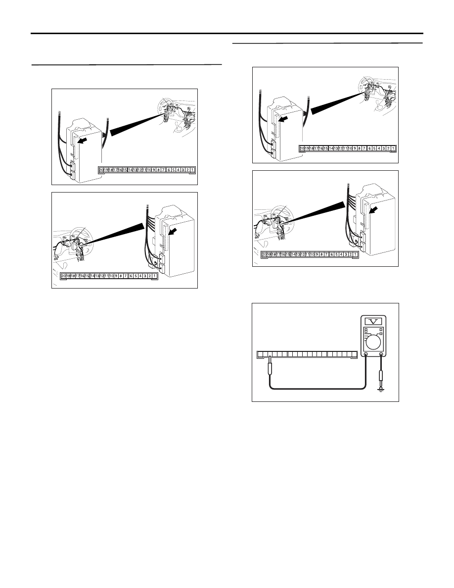
Step 2. Voltage measurement at the C-226
ETACS-ECU connector
(1) Remove the ETACS-ECU, and measure at the
junction block side.
(2) Ignition switch: ACC position
(3) Voltage between C-226 ETACS-ECU connector
terminal No.18 and body earth
OK: System voltage
Q: Is the check result normal?
YES :
Go to Step 4.
NO :
Go to Step 3.
AC310450
Connector: C-226
AB
Junction block side
Junction block (rear view)
<LHD>
AC310461
Junction block (rear view)
Connector: C-226
AB
<RHD>
Junction block side
AC310450
Connector: C-226
AB
Junction block side
Junction block (rear view)
<LHD>
AC310461
Junction block (rear view)
Connector: C-226
AB
<RHD>
Junction block side
AC301541GT
Connector C-226
(Junction block side)
2019
7
13
17
18
1615 14
10
11
12
9 8
2
6 5
3
4
1