Mitsubishi Lancer Evolution IX. Manual - part 248
 

  Index      Mitsubishi     Mitsubishi Lancer Evolution IX - service repair manual


Search            


Content   ..  246  247  248  249   ..


Mitsubishi Lancer Evolution IX. Manual - part 248


SYMPTOM PROCEDURES

SMART WIRING SYSTEM (SWS) USING SWS MONITOR

54C-251

NOTE: 

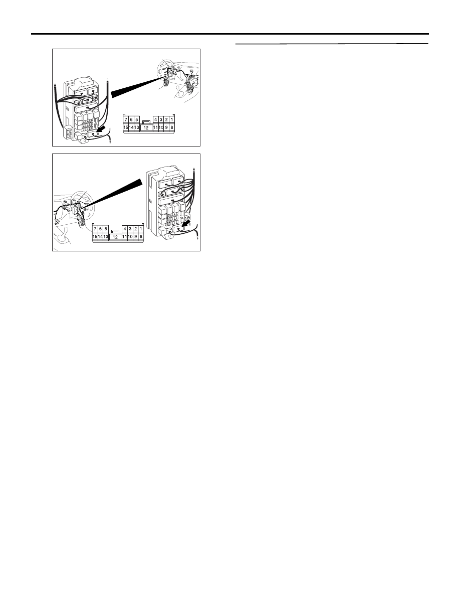
Prior to the wiring harness inspection, check junction 
block connector C-217, and repair if necessary.

• Check the power supply line for open circuit.

Q: Is the check result normal?

YES : 

Go to Step 17.

NO : 

Repair the wiring harness.

Step 17. Retest the system.
Check that the luggage compartment lamp illumi-
nates and extinguishes normally.

Q: Is the check result normal?

YES : 

The trouble can be an intermittent 

malfunction (Refer to GROUP 00 

− How to 

Cope with Intermittent Malfunction 

P.00-5

).

NO : 

Replace the ETACS-ECU.

AC310448

Harness side

Junction block (front view)

Connector: C-217

AC

<LHD>

AC310458

Harness side

Junction block (front view)

Connector: C-217

AC

<RHD>

SYMPTOM PROCEDURES

SMART WIRING SYSTEM (SWS) USING SWS MONITOR

54C-252

INSPECTION PROCEDURE K--2: Interior lamp automatic shutdown function does not work normally.

CAUTION

Whenever the ECU is replaced, ensure that the 
input and output signal circuits are normal.

COMMENTS ON TROUBLE SYMPTOM

The ETACS-ECU operates the interior lamp auto-
matic shutdown function in accordance with the input 
signals below.

• Ignition switch (ACC)

• Ignition switch (IG1)

• Driver's door switch

• All of the door switches

• Interior lamp loaded signal

If this function does not work normally, these input 
signal circuit(s) or the ETACS-ECU may be defec-
tive. Note that this function can be disabled/enabled 
by the adjustment function (default setting; enabled).

POSSIBLE CAUSES

• Malfunction of the door switches

• Malfunction of the room lamp

• Malfunction of the ETACS-ECU

• Damaged harness wires and connectors

DIAGNOSIS PROCEDURE

Step 1. Check the adjustment function.
Check that the interior lamp automatic shutdown 
function has been enabled by using the adjustment 
function.

Q: Is the check result normal?

YES : 

Go to Step 2.

NO : 

Enable the interior lamp automatic 
shutdown function by using the adjustment 
function (Refer to GROUP 54B 

− 

Adjustment function 

P.54B-302

).

INPUT SIGNAL

COMBINATION
METER

KEEP RELAY

LOAD
DETERMINATION
CIRCUIT

LOAD
DETERMINATION
CIRCUIT

· ALL DOOR
  SWITCH
· DRIVER'S DOOR
  SWITCH
· IGNITION
  SWITCH (ACC)
· IGNITION
  SWITCH (IG1)
· INTERIOR LAMP
  LOADED SIGNAL

ETACS-ECU

· FRONT ROOM LAMP
· REAR ROOM LAMP
· LUGGAGE COMPARTMENT LAMP

J/B SIDE

RELAY BOX
(FUSE     )

22

Interior Lamp Automatic Shutdown Function Circuit

SYMPTOM PROCEDURES

SMART WIRING SYSTEM (SWS) USING SWS MONITOR

54C-253

Step 2. ECU check by using the SWS monitor.
Check that the power supply and earth lines to the 
ETACS-ECU and the SWS communication lines are 
normal.

• Ignition switch: OFF

ECUS TO BE CHECKED

• ETACS ECU

OK: "OK" is displayed on the "ETACS ECU" 
menu.

Q: Is the check result normal?

YES : 

Go to Step 3.

NO : 

Refer to Inspection Procedure A-3 
"Communication with the ETACS-ECU is 
not possible 

P.54C-36

."

Step 3. SWS monitor data list.
Check the input signals below, which are related to 
the interior lamp automatic shutdown function.

<Selected item> ETACS ECU

• Ignition switch: OFF

• Driver's door: open

OK: Normal condition is displayed.

Q: Is the check result normal?

Normal conditions are displayed for all the items. : 

Go to Step 4.

Normal condition is not displayed for item No.30. : 

Refer to Inspection Procedure L-2 "The 
ignition switch (IG1) signal is not received 

P.54C-261

."

Normal condition is not displayed for item No.31. : 

Refer to Inspection Procedure L-1 "The 
ignition switch (ACC) signal is not received 

P.54C-258

."

Normal condition is not displayed for item No.32. : 

Refer to Inspection Procedure L-3 "The door 
switch (front: LH) signal is not received <LH 
drive vehicles>

P.54C-263

  ," or refer to 

Inspection Procedure L-3 "The door switch 
(front: RH) signal is not received <RH drive 
vehicles>

P.54C-265

  ."

Step 4. Pulse check.
Check the input signals below, which are related to 
the interior lamp automatic shutdown function.

OK: The M.U.T.-II/III sounds or the voltmeter 
needle fluctuates.

Q: Is the check result normal?

All the signals are received normally. : 

Go to Step 

5.

All the door switch signals are not received. : 

Refer to Inspection Procedure L-11 "All the 
door switch signals are not received <LH 
drive vehicles>

P.54C-289

 ." or refer to 

Inspection Procedure L-11 "All the door 
switch signals are not received <RH drive 
vehicles>

P.54C-292

 ."

The interior lamp loaded signal is not received. : 

Refer to Inspection Procedure L-15 "The 
interior lamp loaded signal is not detected 

P.54C-307

."

Step 5. Retest the system.
Check that the interior lamp automatic shutdown 
function works normally.

Q: Is the check result normal?

YES : 

The trouble can be an intermittent 

malfunction (Refer to GROUP 00 

− How to 

Cope with Intermittent Malfunction 

P.00-5

).

NO : 

Replace the ETACS-ECU.

Item No.

Item name

Normal condition

Item 30

IG SW(IG1)

OFF

Item 31

IG SW(ACC)

OFF

Item 32

DR DOOR SW

ON

System switch

Check condition

All of the door 
switches

A door is opened when all the 
doors are closed

Interior lamp 
loaded signal

When a load is applied through 
multi-purpose fuse No.18

SYMPTOM PROCEDURES

SMART WIRING SYSTEM (SWS) USING SWS MONITOR

54C-254

INSPECTION PROCEDURE K--3: The door-ajar warning lamp does not illuminate/extinguish normally.

CAUTION

Whenever the ECU is replaced, ensure that the 
input and output signal circuits are normal.

OPERATION

The ETACS-ECU operates this function in accord-
ance with all the door switch signals. If the door-ajar 
warning lamp does not work normally, the input sig-
nal circuits from all the door switches or the 
ETACS-ECU may be defective.

POSSIBLE CAUSES

• All the door switches are defective.

• Malfunction of the ETACS-ECU

• Damaged harness wires and connectors

DIAGNOSIS PROCEDURE

Step 1. Check the operation of the room lamp.
Check that the dome lamps illuminate and extinguish 
normally.

Q: Is the check result normal?

YES : 

Go to Step 2.

NO : 

Refer to Inspection Procedure K-1 "The 
front or rear room lamp does not illuminate 
or extinguish normally 

P.54C-244

."

Wire colour code
B : Black     LG : Light green     G : Green     L : Blue     W : White     Y : Yellow     SB : Sky blue
BR : Brown     O : Orange     GR : Gray     R : Red     P : Pink     V : Violet

ETACS-ECU

· ALL DOOR SWITCH

INPUT SIGNAL

COMBINATION
METER

· DRIVER'S DOOR SWITCH

Door Ajar Indicator Lamp Circuit


Content   ..  246  247  248  249   ..