Mitsubishi Lancer Evolution IX. Manual - part 198
 

  Index      Mitsubishi     Mitsubishi Lancer Evolution IX - service repair manual


Search            


Content   ..  196  197  198  199   ..


Mitsubishi Lancer Evolution IX. Manual - part 198


SYMPTOM PROCEDURES

SMART WIRING SYSTEM (SWS) USING SWS MONITOR

54C-51

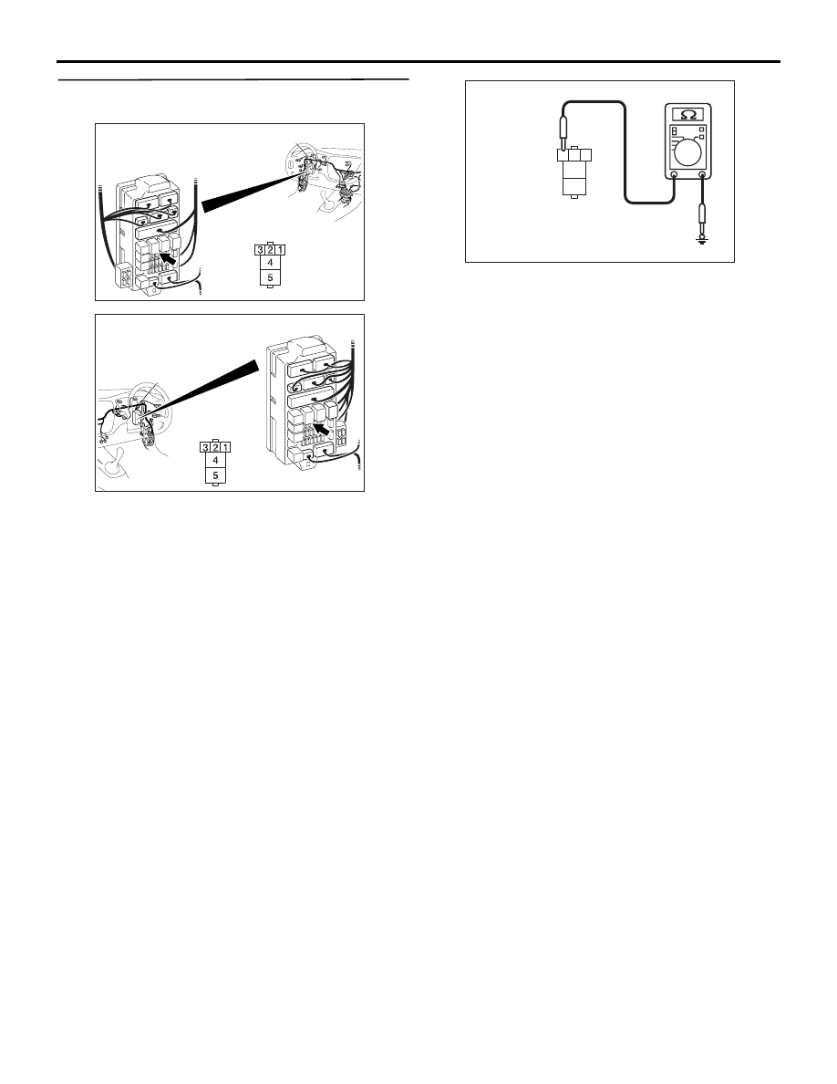
Step 9. Resistance measurement at C-224 power 
window relay connector

(1) Remove the power window relay, and measure at 

the junction block side.

(2) Resistance between C-224 power window relay 

connector terminal No.3 and body earth

OK: 2 

 or less

Q: Is the check result normal?

YES : 

Go to Step 11.

NO : 

Go to Step 10.

AC310448

AI

Connector: C-224 <LHD>

Junction block (front view)

Junction block side

AC310458

AG

Connector: C-224 <RHD>

Junction block (front view)

Junction block 
side

AC310506AL

Connector C-224 
(Junction block side)

3

4

5

1

2

SYMPTOM PROCEDURES

SMART WIRING SYSTEM (SWS) USING SWS MONITOR

54C-52

Step 10. Check the wiring harness between C-224 
power window relay connector terminal No.3 and 
body earth.

NOTE: Prior to the wiring harness inspection, check 
junction block connector C-214, and repair if neces-
sary.

• Check the earth wires for open circuit.

Q: Is the check result normal?

YES : 

The trouble can be an intermittent 

malfunction (Refer to GROUP 00 

− How to 

Cope with Intermittent Malfunction 

P.00-5

).

NO : 

Repair the wiring harness.

Step 11. Connector check: C-226 ETACS-ECU 
connector

Q: Is the check result normal?

YES : 

Go to Step 12.

NO : 

Repair the defective connector.

AC310449

Junction block side

Junction block (front view)

Connectors: C-214, C-224 <LHD>

C-214

C-224

Harness side

C-224

C-214

AO

AC310459

Junction block side

Junction block (front view)

Connectors: C-214, C-224 <RHD>

C-214

C-224

Harness side

C-224

C-214

AO

AC310450

Connector: C-226 <LHD>

AB

Junction block side

Junction block (rear view)

AC310461

Connector: C-226 <RHD>

AE

Junction block side

Junction block 
(rear view)

SYMPTOM PROCEDURES

SMART WIRING SYSTEM (SWS) USING SWS MONITOR

54C-53

Step 12. Check the wiring harness between C-224 
power window relay connector terminal No.4 and 
E-05 power window main switch connector 
terminal No.6.

NOTE: 

Prior to the wiring harness inspection, check interme-
diate connectors C-17 <LH drive vehicles> or C-110 
<RH drive vehicles> and junction block connector 
C-211, and repair if necessary.

• Check the power supply line for open circuit.

Q: Is the check result normal?

YES : 

The trouble can be an intermittent 

malfunction (Refer to GROUP 00 

− How to 

Cope with Intermittent Malfunction 

P.00-5

).

NO : 

Repair the wiring harness.

AC310448

AI

Connector: C-224 <LHD>

Junction block (front view)

Junction block side

AC310458

AG

Connector: C-224 <RHD>

Junction block (front view)

Junction block 
side

AC310484

Connector: E-05 <LHD>

AD

Harness side

10

1

6

14

5

12

13

4

11

7

2

3

8

9

Front door (LH)

AC310493

Connector: E-05 <RHD>

AG

Harness side

10

1

6

14

5

12

13

4

11

7

2

3

8

9

Front door (RH)

AC310446

Connector: C-17 <LHD>

AE

AC310456

Connector: C-110 <RHD>

AH

AC310448

AJ

Connector: C-211 <LHD>

Junction block (front view)

Harness side

AC310458

AI

Connector: C-211 <RHD>

Junction block (front view)

Harness side

SYMPTOM PROCEDURES

SMART WIRING SYSTEM (SWS) USING SWS MONITOR

54C-54

Step 13. Resistance measurement at the E-05 
power window main switch connector

(1) Disconnect the connector, and measure at the 

wiring harness side.

(2) Resistance between E-05 power window main 

switch connector terminal No.2 and body earth

OK: 2 

 or less

Q: Is the check result normal?

YES : 

Go to Step 15.

NO : 

Go to Step 14.

Step 14. Check the wiring harness between E-05 
power window main switch connector terminal 
No.2 and body earth.

NOTE: 

Prior to the wiring harness inspection, check interme-
diate connectors C-17 <LH drive vehicles> or C-110 
<RH drive vehicles>, and repair if necessary.

• Check the earth wires for open circuit.

AC310484

Connector: E-05 <LHD>

AD

Harness side

10

1

6

14

5

12

13

4

11

7

2

3

8

9

Front door (LH)

AC310493

Connector: E-05 <RHD>

AG

Harness side

10

1

6

14

5

12

13

4

11

7

2

3

8

9

Front door (RH)

AC301541BI

Connector E-05
(Harness side)

10

1

6

14

5

12

13

4

11

7

2

3

8

9

AC310484

Connector: E-05 <LHD>

AD

Harness side

10

1

6

14

5

12

13

4

11

7

2

3

8

9

Front door (LH)

AC310493

Connector: E-05 <RHD>

AG

Harness side

10

1

6

14

5

12

13

4

11

7

2

3

8

9

Front door (RH)

AC310446

Connector: C-17 <LHD>

AE

AC310456

Connector: C-110 <RHD>

AH


Content   ..  196  197  198  199   ..