Mitsubishi Lancer Evolution IX. Manual - part 196
SYMPTOM PROCEDURES
SMART WIRING SYSTEM (SWS) USING SWS MONITOR
54C-43
COMMENTS ON TROUBLE SYMPTOM
It is suspected that the power supply circuit to the
front-ECU is defective, or the wiring harness
between the SWS monitor and the front-ECU or their
connector(s) is damaged. If the battery power supply
circuit to the ECU (terminal No.5 of the front-ECU) is
damaged, also check the power supply circuit from
the ignition switch (IG2) (terminal No.22 of the
front-ECU), and repair if necessary.
POSSIBLE CAUSES
• Malfunction of the front-ECU
• Malfunction of the ETACS-ECU
• Damaged harness wires and connectors
DIAGNOSIS PROCEDURE
Step 1. ECU check by using the SWS monitor.
Check that the power supply and earth lines to the
ETACS-ECU and the SWS communication lines are
normal.
• Ignition switch: OFF
ECUS TO BE CHECKED
• ETACS ECU
OK: "OK" is displayed on the "ETACS ECU"
menu.
Q: Is the check result normal?
YES :
Go to Step 2.
NO :
Refer to Inspection Procedure A-3
"Communication with the ETACS-ECU is
not possible
Step 2. Connector check: A-10X front-ECU
connector
Q: Is the check result normal?
YES :
Go to Step 3.
NO :
Repair the defective connector.
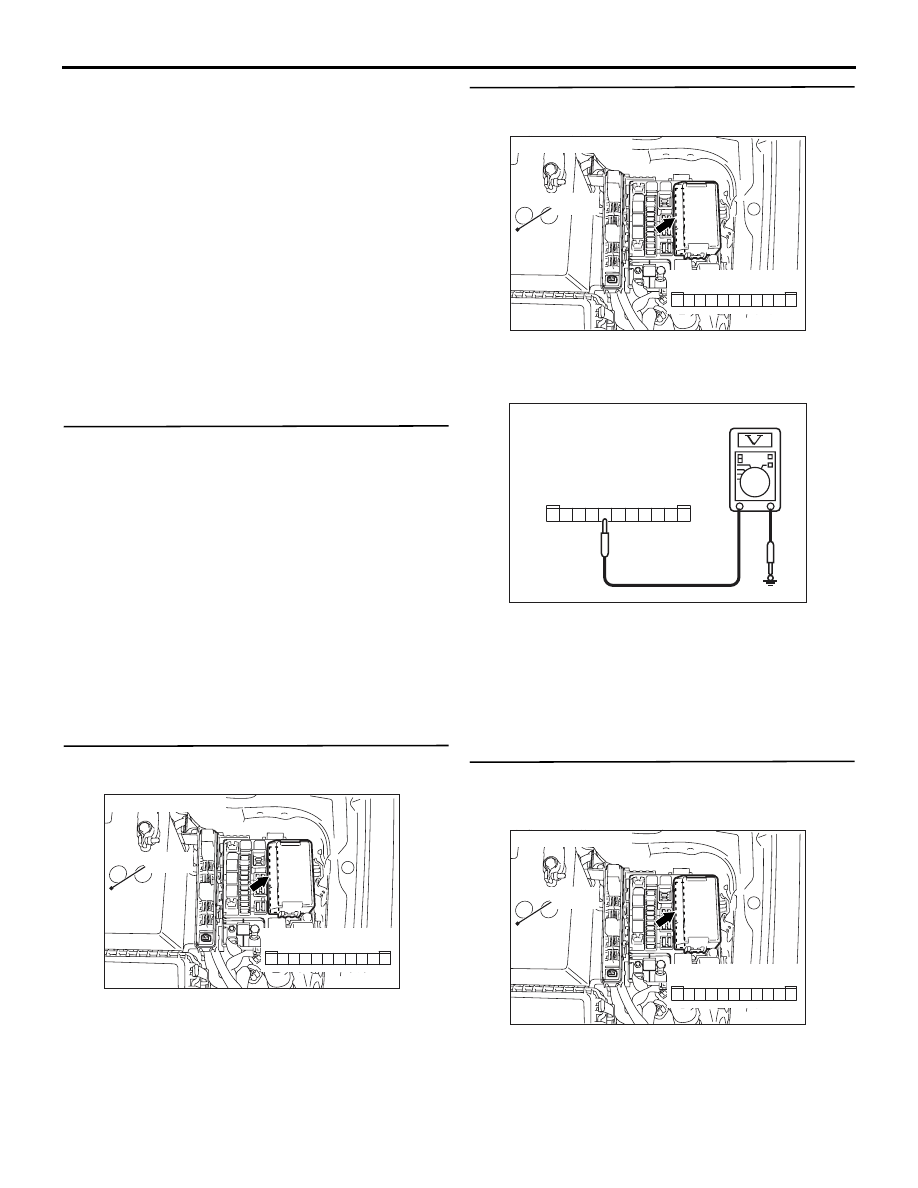
Step 3. Voltage measurement at A-10X front-ECU
connector
(1) Disconnect the connector, and measure at the
relay box side.
(2) Ignition switch: ON
(3) Voltage between A-10X front-ECU connector
terminal No.7 and body earth
OK: System voltage
Q: Is the check result normal?
YES :
Go to Step 6.
NO :
Go to Step 4.
Step 4. Check the wiring harness between A-10X
front-ECU connector terminal No.7 and the
battery.
• Check the power supply line for open circuit.
AC310572AB
Connector: A-10X
Relay box side
10
11
5
9 8 7 6
4 3
1
2
Battery
AC310572AB
Connector: A-10X
Relay box side
10
11
5
9 8 7 6
4 3
1
2
Battery
AC301541CT
5
11
9
10
8 7 6
2
4 3
1
Connector A-10X
(Relay box side)
AC310572AB
Connector: A-10X
Relay box side
10
11
5
9 8 7 6
4 3
1
2
Battery