Mitsubishi Lancer Evolution IX. Manual - part 194
 

  Index      Mitsubishi     Mitsubishi Lancer Evolution IX - service repair manual


Search            


Content   ..  192  193  194  195   ..


Mitsubishi Lancer Evolution IX. Manual - part 194


SYMPTOM PROCEDURES

SMART WIRING SYSTEM (SWS) USING SWS MONITOR

54C-35

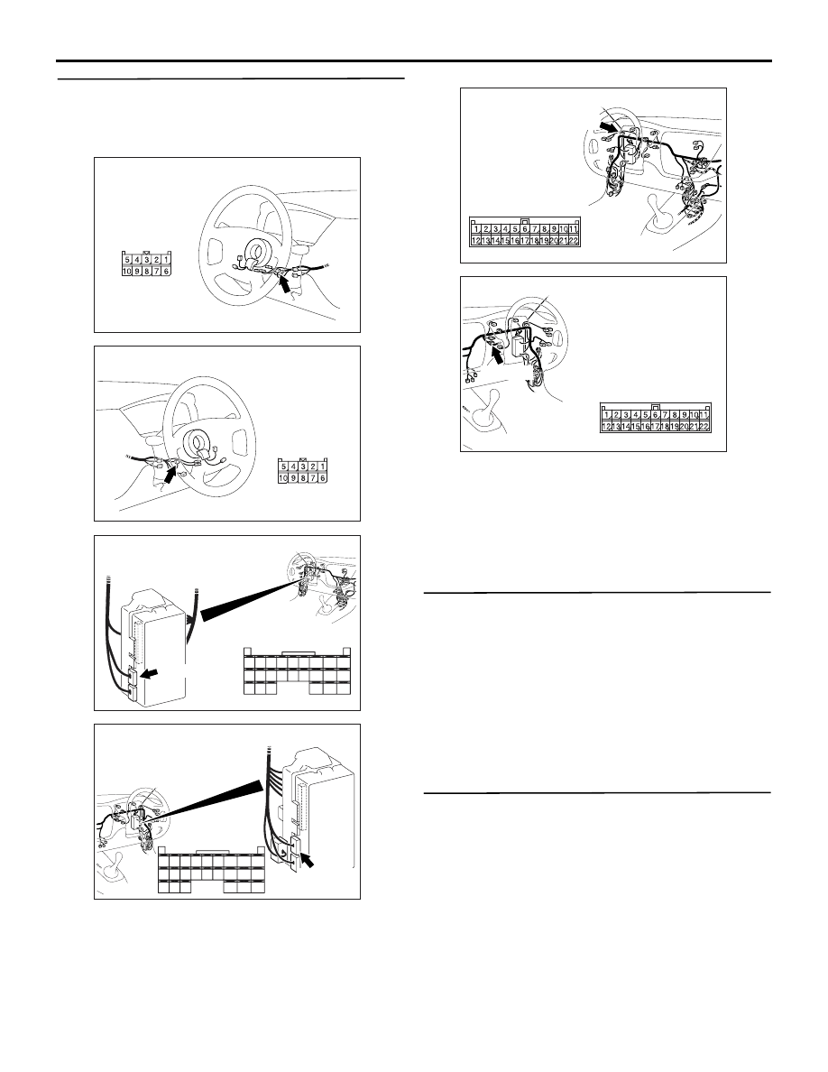
Step 8. Check the wiring harness from C-228 
ETACS-ECU connector terminal Nos.59 and 68 to 
C-206 column switch connector terminal Nos.3 
and 2.

NOTE: 

Prior to the wiring harness inspection, check joint 
connector C-101, and repair if necessary.

• Check the communication lines for open circuit.

Q: Is the check result normal?

YES : 

Go to Step 9.

NO : 

Repair the wiring harness.

Step 9. ECU check by using the SWS monitor.

• Ignition switch: OFF

ECUS TO BE CHECKED

• COLUMN ECU

OK: "OK" is displayed on the "COLUMN 
ECU" menu.

Q: Is the check result normal?

YES : 

Go to Step 10.

NO : 

Replace the column switch.

Step 10. Retest the system.
Check that the ETACS-ECU communicates with the 
column switch.

Q: Is the check result normal?

YES : 

The trouble can be an intermittent 

malfunction (Refer to GROUP 00 

− How to 

Cope with Intermittent Malfunction 

P.00-5

).

NO : 

Replace the ETACS-ECU.

AC310479

AD

Connector: C-206 <LHD>

Harness side

AC310481AD

Connector: C-206 <RHD>

Harness side

AC310450

Connector: C-228 <LHD>

AC

Junction block (rear view)

C-228 (GR)

Harness side

51

52

53

54

55

56

57

58

59

60

61

62

63

64

65

66

67

68

69

70

71

72

73

74

AC310461

Junction block (rear view)

Connector: C-228 <RHD>

AC

Harness side

C-228 (GR)

51

52

53

54

55

56

57

58

59

60

61

62

63

64

65

66

67

68

69

70

71

72

73

74

AC310446

Connector: C-101 <LHD>

AW

C-101 (L)

AC310456

Connector: C-101 <RHD>

AQ

C-101 (L)

SYMPTOM PROCEDURES

SMART WIRING SYSTEM (SWS) USING SWS MONITOR

54C-36

INSPECTION PROCEDURE A-3: Communication with the ETACS-ECU is not possible.

CAUTION

Whenever the ECU is replaced, ensure that the 

power supply circuit, the earthing circuit and the 

communication circuit are normal.

ETACS-ECU Power Supply and SWS Communication Circuit

Wire colour code
B : Black     LG : Light green
G : Green     L : Blue      
W : White     Y : Yellow
SB : Sky blue     BR : Brown 
O : Orange     GR : Grey  
R : Red     P : Pink     
V : Violet     PU : Purple

IGNITION 
SWITCH (IG1)

POWER 
SOURCE

ETACS-
ECU

COLUMN-ECU

COLUMN 
SWITCH

BATTERY

RELAY
BOX

J/B SIDE

SYMPTOM PROCEDURES

SMART WIRING SYSTEM (SWS) USING SWS MONITOR

54C-37

COMMENTS ON TROUBLE SYMPTOM

It is suspected that the power supply circuit to the 
ETACS-ECU is defective, or the wiring harness 
between the SWS monitor and the ETACS-ECU or 
their connector(s) is damaged. If the battery power 
supply circuit to the ECU (terminal No.20 of the 
ETACS-ECU) is damaged, also check the power 
supply circuit from the ignition switch (IG1) (terminal 
No.8 of the ETACS-ECU), and repair if necessary. If 
the earth circuit to the ECU (terminal No.3 of the 
ETACS-ECU) is defective, also check the earth cir-
cuit to the sensor (terminal No.56 of the 
ETACS-ECU), and repair if necessary.

TROUBLESHOOTING HINTS

• Malfunction of the ETACS-ECU

• Damaged harness wires and connectors

DIAGNOSIS PROCEDURE

Step 1. Connector check: C-226 ETACS-ECU 
connector

Q: Is the check result normal?

YES : 

Go to Step 2.

NO : 

Repair the defective connector.

Step 2. Voltage measurement at the C-226 
ETACS-ECU connector

(1) Remove the ETACS-ECU, and measure at the 

junction block side.

(2) Voltage between C-226 ETACS-ECU connector 

terminal No.20 and body earth

OK: System voltage

Q: Is the check result normal?

YES : 

Go to Step 4.

NO : 

Go to Step 3.

AC310450

Connector: C-226 <LHD>

AB

Junction block side

Junction block (rear view)

AC310461

Connector: C-226 <RHD>

AE

Junction block side

Junction block 
(rear view)

AC310450

Connector: C-226 <LHD>

AB

Junction block side

Junction block (rear view)

AC310461

Connector: C-226 <RHD>

AE

Junction block side

Junction block 
(rear view)

AC310507AB

Connector C-226 
(Junction block side)

2019

7

13

17

18

1615 14

10

11

12

9 8

2

6 5

3

4

1

SYMPTOM PROCEDURES

SMART WIRING SYSTEM (SWS) USING SWS MONITOR

54C-38

Step 3. Check the wiring harness between C-226 
ETACS-ECU connector terminal No.20 and 
battery.

NOTE: 

Prior to the wiring harness inspection, check joint 
connector C-05, intermediate connector C-129 and 
junction block connector C-210, and repair if neces-
sary.

• Check the power supply line for open circuit.

Q: Is the check result normal?

YES : 

The trouble can be an intermittent 

malfunction (Refer to GROUP 00 

− How to 

Cope with Intermittent Malfunction 

P.00-5

).

NO : 

Repair the wiring harness.

AC310450

Connector: C-226 <LHD>

AB

Junction block side

Junction block (rear view)

AC310461

Connector: C-226 <RHD>

AE

Junction block side

Junction block 
(rear view)

AC310447

Connectors: C-05, C-129 <LHD>

C-05 (GR)

C-129

C-05

C-129

AC

AC310455

Connectors: C-05, C-129 <RHD>

C-05 (GR)

C-129

C-05

C-129

AB

AC310448

Harness side

Junction block (front view)

Connector: C-210 <LHD>

AD

10

1

6

14

5

12

13

4

11

7

2

3

8

9

AC310458

Harness side

Junction block (front view)

Connector: C-210 <RHD>

AD

10

1

6

14

5

12

13

4

11

7

2

3

8

9


Content   ..  192  193  194  195   ..