Mitsubishi Lancer Evolution IX. Manual - part 155
 

  Index      Mitsubishi     Mitsubishi Lancer Evolution IX - service repair manual


Search            


Content   ..  153  154  155  156   ..


Mitsubishi Lancer Evolution IX. Manual - part 155


SYMPTOM PROCEDURES

SMART WIRING SYSTEM (SWS) NOT USING SWS MONITOR

54B-183

DIAGNOSTIC PROCEDURE

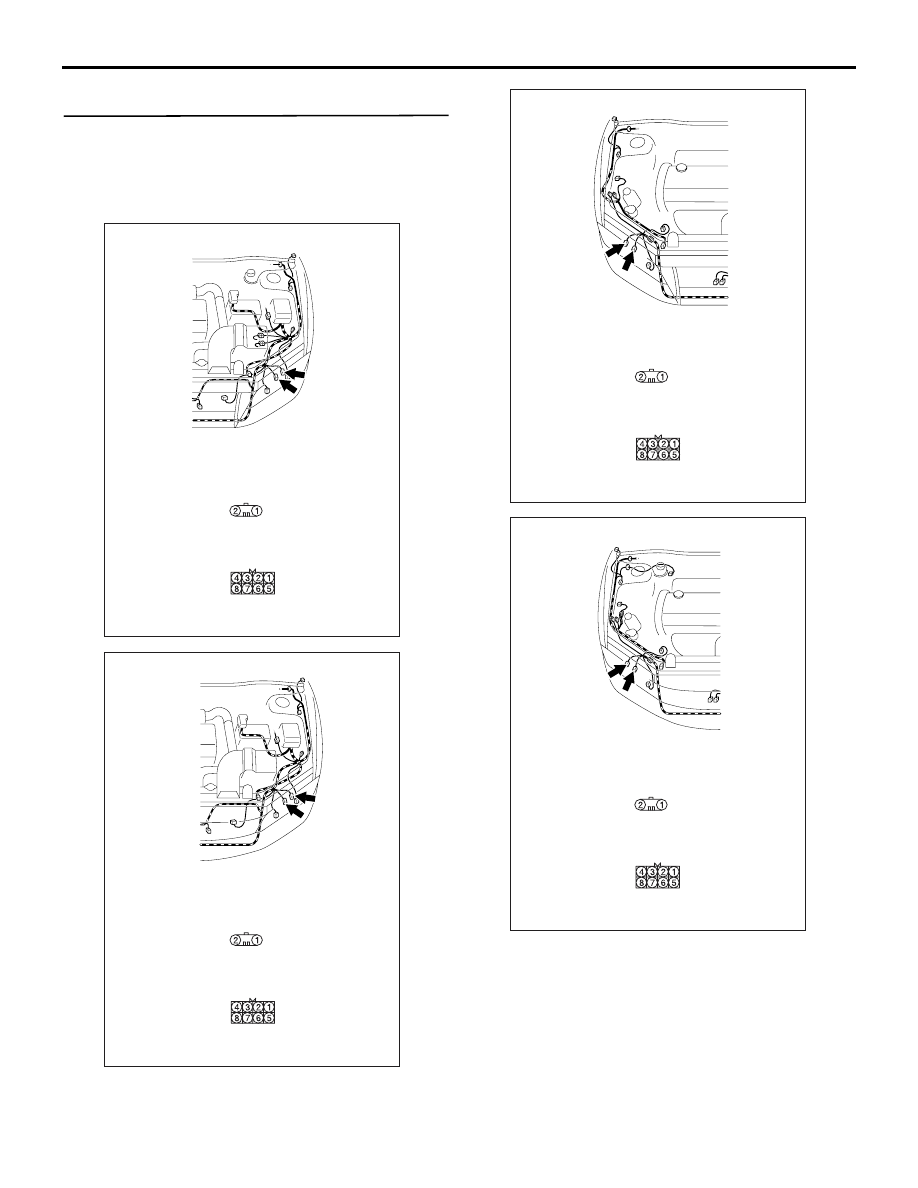
Step 1. Connector check: A-31 <headlamp (LO) 
RH>, A-39 <headlamp (LO) LH>, A-21 <headlamp 
(HI) RH>, A-15 <headlamp (HI) LH> headlamp 
assembly connector or C-01 <high-beam 
indicator> combination meter connector

AC310543

Connectors: A-15, A-31

AC

<LHD>

A-15

Harness side

A-31

Harness side

A-15

A-31

AC310476

Connectors: A-15, A-31

AC

<RHD>

A-15

Harness side

A-31

Harness side

A-15

A-31

AC310432

Connectors: A-21, A-39

AC

<LHD>

A-21

Harness side

A-39

Harness side

A-21

A-39

AC310434

Connectors: A-21, A-39

AC

<RHD>

A-21

Harness side

A-39

Harness side

A-21

A-39

SYMPTOM PROCEDURES

SMART WIRING SYSTEM (SWS) NOT USING SWS MONITOR

54B-184

Q: Is the check result normal?

YES : 

Go to Step 2.

NO : 

Repair the defective connector.

Step 2. Check the bulb(s) of the headlamps or the 
high-beam indicator lamp.
Check the bulb(s) of the defective lamp.

Q: Is the check result normal?

YES : 

Go to Step 3.

NO : 

Replace the bulb(s) of the defective lamp.

AC310446

Connector: C-01
<LHD>

AM

Harness side

AC310456

Connector: C-01
<RHD>

AL

Harness side

SYMPTOM PROCEDURES

SMART WIRING SYSTEM (SWS) NOT USING SWS MONITOR

54B-185

Step 3. Resistance measurement at A-31 
<headlamp (LO) RH>, A-39 <headlamp (LO) LH>, 
A-21 <headlamp (HI) RH>, A-15 <headlamp (HI) 
LH> headlamp assembly connector or C-01 
<high-beam indicator> combination meter 
connector

AC310543

Connectors: A-15, A-31

AC

<LHD>

A-15

Harness side

A-31

Harness side

A-15

A-31

AC310476

Connectors: A-15, A-31

AC

<RHD>

A-15

Harness side

A-31

Harness side

A-15

A-31

AC310432

Connectors: A-21, A-39

AC

<LHD>

A-21

Harness side

A-39

Harness side

A-21

A-39

AC310434

Connectors: A-21, A-39

AC

<RHD>

A-21

Harness side

A-39

Harness side

A-21

A-39

SYMPTOM PROCEDURES

SMART WIRING SYSTEM (SWS) NOT USING SWS MONITOR

54B-186

(1) Disconnect the connector, and measure at the 

wiring harness side.

(2) Check the resistance between the lamp 

connector and body earth.

Resistance between A-31 <headlamp (LO) RH> 

headlamp assembly connector terminal No.8 
and body earth

• Resistance between A-39 <headlamp (LO) 

LH> headlamp assembly connector terminal 
No.8 and body earth

Resistance between A-21 <headlamp (HI) RH> 

headlamp assembly connector terminal No.2 
and body earth

• Resistance between A-15 <headlamp (HI) 

LH> headlamp assembly connector terminal 
No.2 and body earth

Resistance between C-01 <high-beam indicator> 

combination meter connector terminal No.5 
and body earth

OK: 2 

 or less

Q: Is the check result normal?

YES : 

Go to Step 5.

NO : 

Go to Step 4.

AC310446

Connector: C-01
<LHD>

AM

Harness side

AC310456

Connector: C-01
<RHD>

AL

Harness side

AC301541HJ

Connector A-31, A-39
(Harness side)

AC301541HK

Connector A-15, A-21
(Harness side)

AC301541HL

Connector C-01
(Harness side)


Content   ..  153  154  155  156   ..