Mitsubishi Lancer Evolution IX. Manual - part 132
 

  Index      Mitsubishi     Mitsubishi Lancer Evolution IX - service repair manual


Search            


Content   ..  130  131  132  133   ..


Mitsubishi Lancer Evolution IX. Manual - part 132


SYMPTOM PROCEDURES

SMART WIRING SYSTEM (SWS) NOT USING SWS MONITOR

54B-91

Q: Is the check result normal?

YES : 

Go to Step 11.

NO : 

Repair the wiring harness.

Step 11. Retest the system.
After the front power window sub switch is replaced, 
check that the front passenger's door power window 
can be operated by the front power window sub 
switch.
(1) Replace the front power window sub switch.
(2) Check that the front passenger's door power 

window can be operated by the front power 
window sub switch.

Q: Is the check result normal?

YES : 

The trouble can be an intermittent 

malfunction (Refer to GROUP 00 

− How to 

Cope with Intermittent Malfunction 

P.00-5

).

NO : 

Replace the front power window regulator 
motor assembly (RH).

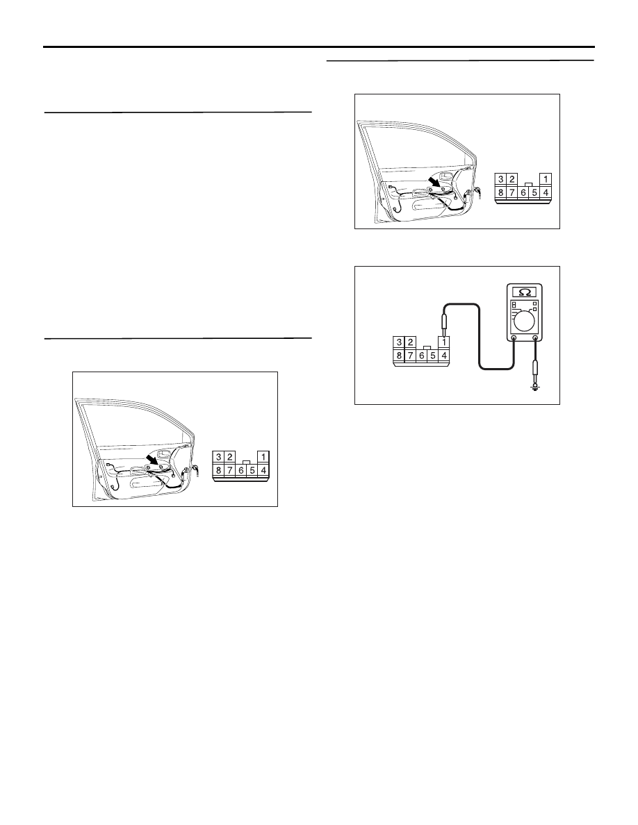
Step 12. Connector check: E-14 front power 
window sub switch connector

Q: Is the check result normal?

YES : 

Go to Step 13.

NO : 

Repair the connector.

Step 13. Resistance measurement at E-14 front 
power window sub switch connector

(1) Disconnect the connector, and measure at the 

wiring harness side.

(2) Resistance between E-14 front power window 

sub switch connector terminal No.1 and body 
earth

OK: 2

 or less

Q: Is the check result normal?

YES : 

Go to Step 15.

NO : 

Go to Step 14.

AC310498

Connector: E-14 <RHD>

Harness side

AC

Front door (LH)

AC310498

Connector: E-14 <RHD>

Harness side

AC

Front door (LH)

AC310506

Connector E-14
(Harness side)

AE

SYMPTOM PROCEDURES

SMART WIRING SYSTEM (SWS) NOT USING SWS MONITOR

54B-92

Step 14. Check the wiring harness from E-14 
front power window sub switch connector 
terminal No.1 to body earth.

NOTE: 

Prior to the wiring harness inspection, check interme-
diate connector C-17, and repair if necessary.

• Check the earth wires for open circuit.

Q: Is the check result normal?

YES : 

The trouble can be an intermittent 

malfunction (Refer to GROUP 00, How to 
Cope with Intermittent Malfunction 

P.00-5

).

NO : 

Repair the wiring harness.

Step 15. Voltage measurement at E-14 front 
power window sub switch connector

(1) Disconnect the connector, and measure at the 

wiring harness side.

(2) Turn the ignition switch to the ON position.

(3) Voltage between E-14 front power window sub 

switch connector terminal No.4 and body earth

OK: System voltage

Q: Is the check result normal?

YES : 

Go to Step 18.

NO : 

Go to Step 16.

Step 16. Connector check: C-224 power window 
relay connector

Q: Is the check result normal?

YES : 

Go to Step 17.

NO : 

Repair the connector.

AC310498

Connector: E-14 <RHD>

Harness side

AC

Front door (LH)

AC310454

Connector: C-17 <RHD>

AH

AC310498

Connector: E-14 <RHD>

Harness side

AC

Front door (LH)

AC310507

Connector E-14 
(Harness side)

AD

AC310458

AG

Connector: C-224 <RHD>

Junction block (front view)

Junction block 
side

SYMPTOM PROCEDURES

SMART WIRING SYSTEM (SWS) NOT USING SWS MONITOR

54B-93

Step 17. Check the wiring harness from E-14 
front power window sub switch connector 
terminal No.4 to C-224 power window relay 
connector terminal No.4.

NOTE: 

Prior to the wiring harness inspection, check interme-
diate connectors C-17 and junction block connector 
C-211, and repair if necessary.

• Check the power supply line for open circuit.

Q: Is the check result normal?

YES : 

The trouble can be an intermittent 

malfunction (Refer to GROUP 00, How to 
Cope with Intermittent Malfunction 

P.00-5

).

NO : 

Repair the wiring harness.

Step 18. Connector check: E-02 front power 
window regulator motor (LH) connector

Q: Is the check result normal?

YES : 

Go to Step 19.

NO : 

Repair the connector.

Step 19. Check the wiring harness from E-02 
front power window regulator motor (LH) 
connector terminal Nos.1 and 4 to E-14 front 
power window sub switch connector terminal 
Nos.5 and 7.

• Check the input and output lines for open or short 

circuit.

AC310498

Connector: E-14 <RHD>

Harness side

AC

Front door (LH)

AC310459

AD

Connectors: C-211, C-224 <RHD>

Junction block (front view)

Junction block side

C-211

C-224

C-224

Harness side

C-211

AC310454

Connector: C-17 <RHD>

AH

AC310498

Connector: E-02 <RHD>

Harness side

E-02 (GR)

AD

Front door (LH)

AC310499

Connectors: E-02, E-14 <RHD>

E-14

E-02

Harness side

Harness side

E-14

E-02 (GR)

AB

Front door (LH)

SYMPTOM PROCEDURES

SMART WIRING SYSTEM (SWS) NOT USING SWS MONITOR

54B-94

Q: Is the check result normal?

YES : 

Go to Step 20.

NO : 

Repair the wiring harness.

Step 20. Retest the system.
After the front power window sub switch is replaced, 
check that the front passenger's door power window 
can be operated by the front power window sub 
switch.
(1) Replace the front power window sub switch.
(2) Check that the front passenger's door power 

window can be operated by the front power 
window sub switch.

Q: Is the check result normal?

YES : 

The trouble can be an intermittent 

malfunction (Refer to GROUP 00 

− How to 

Cope with Intermittent Malfunction 

P.00-5

).

NO : 

Replace the front power window regulator 
motor assembly (LH).

Step 21. Connector check: E-17 rear power 
window sub switch (RH) connector

Q: Is the check result normal?

YES : 

Go to Step 22.

NO : 

Repair the connector.

Step 22. Resistance measurement at E-17 rear 
power window sub switch (RH) connector

(1) Disconnect the connector, and measure at the 

wiring harness side.

(2) Resistance between E-17 rear power window sub 

switch (RH) connector terminal No.1 and body 
earth

OK: 2

 or less

Q: Is the check result normal?

YES : 

Go to Step 24.

NO : 

Go to Step 23.

AC310491

Connector: E-17

AC

Harness side

Rear door (RH)

AC310491

Connector: E-17

AC

Harness side

Rear door (RH)

AC310506

Connector E-17 
(Harness side)

AF


Content   ..  130  131  132  133   ..