Mitsubishi Eclipse / Eclipse Spyder (2000-2002). Service and repair manual - part 695
 

  Index      Mitsubishi     Mitsubishi Eclipse / Eclipse Spyder (2000-2002). Service and repair manual


Search            


Content   ..  693  694  695  696   ..


Mitsubishi Eclipse / Eclipse Spyder (2000-2002). Service and repair manual - part 695


MANUAL A/C DIAGNOSIS

TSB Revision

HEATING AND AIR CONDITIONING

55-17

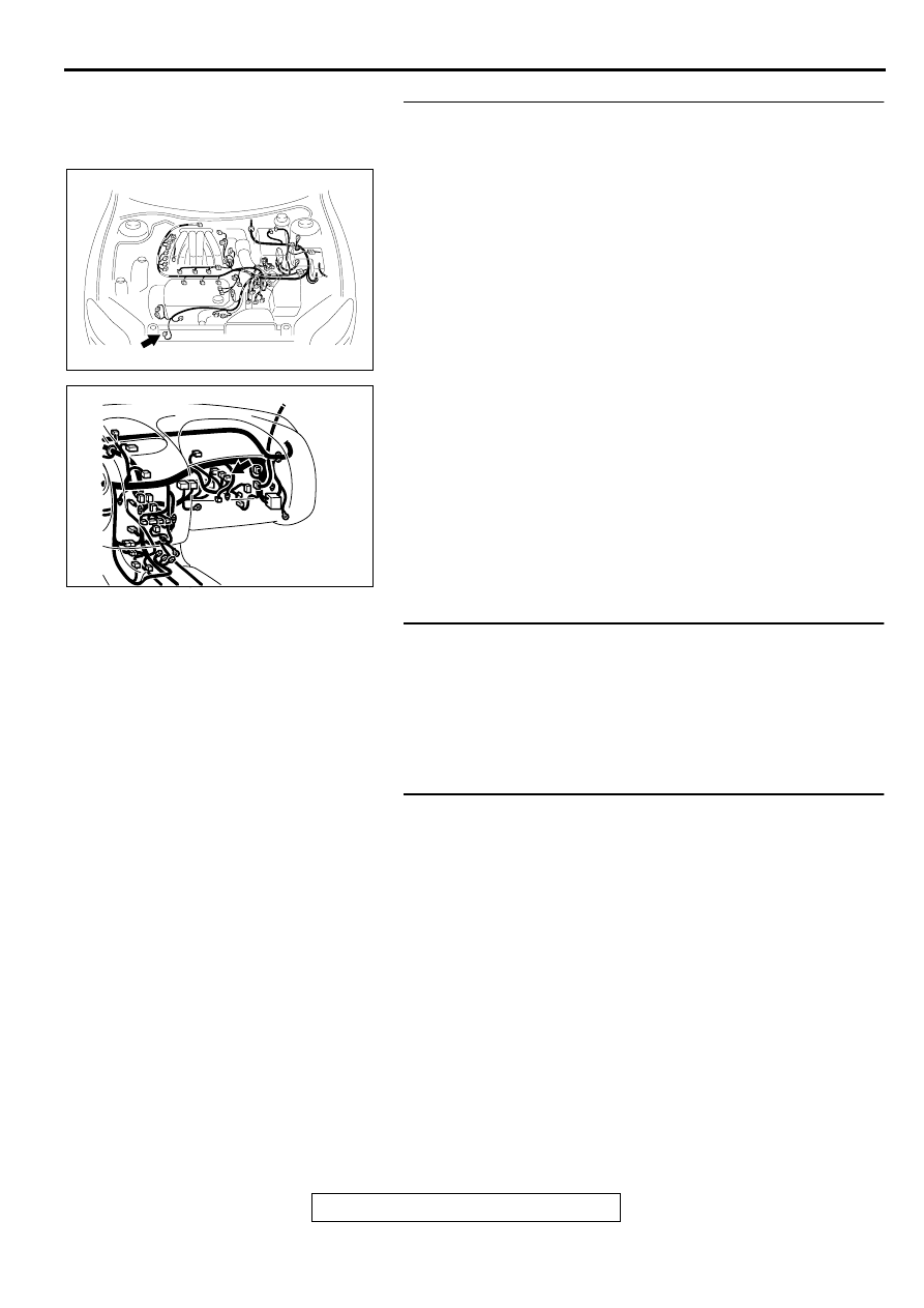
STEP 3. Check the harness wire between the compressor 
connector B-18 and automatic compressor controller 
connector C-13.
Q: Is the harness wire between the compressor connector 

B-18 and automatic compressor controller connector C-
13 in good condition?
YES : 
Go to Step 4.
NO :  Repair. Then go to Step 4.

STEP 4. Measure the automatic compressor controller 
terminal voltage.
Refer to 

P.55-18

.

Q: Is the automatic compressor controller terminal voltage 

in good condition?
YES : 
Go to Step 5.
NO :  Replace. Then go to Step 5.

STEP 5. Check symptoms.

Q: Does the A/C indicator flashes?

YES : Go to Step 1.
NO :  This diagnosis is complete. (If no malfunctions are not 

found in all steps, an intermittent malfunction is 
suspected. Refer to GROUP 00E, How to Use 
Troubleshooting/Inspection Service Points 

 How to 

Cope with Intermittent Malfunction 

P.00-6

.)

AC003666 AB

CONNECTOR: B-18

AC002282AE

CONNECTOR: C-13

MANUAL A/C DIAGNOSIS

TSB Revision

HEATING AND AIR CONDITIONING

55-18

CHECK AT ECU TERMINAL

M1552010300077

1

2 3 4 5 6

7 8

9 10

11 12 13 14 15 16 17 18 19 20

21 22 23 24

25 26 27 28

AC002292AB

TERMINAL 
NO.

CHECK ITEM

CHECKING REQUIREMENTS

NORMAL CONDITION

1

Power supply

Ignition switch: "LOCK" (OFF)

0 V

Ignition switch: "ON"

Battery positive voltage

2

Input from thermistor sensor to 
controller

Ignition switch and A/C switch: 
OFF

0 V

Ignition switch and A/C switch: 
ON

 5 V

3

Thermistor sensor power supply Ignition switch and A/C switch: 

OFF

0 V

Ignition switch and A/C switch: 
ON

5 V

4, 5

Output from controller to 
engine control module <M/T>/
powertrain control module 
<A/T>

Air thermistor sensor detection 
temperature: 5

°

C (41.0

°

F) or 

less

0 V

Air thermistor sensor detection 
temperature: 55C (46.45F) or 
less

Battery positive voltage

6

-

-

-

7

Input from A/C switch (outside/
inside air selection damper 
control switch) to controller

Outside air switch: ON

Inside air switch: OFF

0 V

Outside air switch: OFF

Inside air switch: ON

Battery positive voltage

8

Input from defroster switch 
(FOOT) to controller

Defroster switch (FOOT): ON

0 V

Defroster switch (FOOT): OFF

Battery positive voltage

9

Input from defroster switch 
(DEF) to controller

Defroster switch (DEF): ON

0 V

Defroster switch (DEF): OFF

Battery positive voltage

10Input from A/C switch to 

controller

A/C switch: OFF

0 V

A/C switch: ON

Battery positive voltage

11

Ground

Always

0 V

12

-

-

-

13

Input from A/C switch (outside/
inside air selection damper 
control switch) to controller

Outside air switch: ON

Inside air switch: OFF

Battery positive voltage

Outside air switch: OFF

Inside air switch: ON

0 V

14

Input from A/C switch (IND) to 
controller

A/C switch: OFF

0 V

A/C switch: ON

Battery positive voltage

15

-

-

-

MANUAL A/C DIAGNOSIS

TSB Revision

HEATING AND AIR CONDITIONING

55-19

TROUBLESHOOTING HINT

M1552013400040

Condenser fan and radiator fan control

Refer to GROUP 14, Diagnosis 

 Symptom 

Chart

P.14-3

.

Compressor control

Refer to 

P.55-3

.

16

Output from controller to 
outside/inside air selection 
damper control motor

Outside air switch: ON

Inside air switch: OFF

Battery positive voltage

Outside air switch: OFF

Inside air switch: ON

0 V

17

Output from controller to 
outside/inside air selection 
damper control motor

Outside air switch: ON

Inside air switch: OFF

0 V

Outside air switch: OFF

Inside air switch: ON

Battery positive voltage

18

Input from taillight relay to 
controller

Taillight relay: OFF

0 V

Taillight relay: ON

Battery positive voltage

19

Input from blower switch (LO) to 
controller

Blower switch (LO): OFF

0 V

Blower switch (LO): ON

Battery positive voltage

20

-

-

-

21

Input from A/C compressor 
relay to controller

A/C compressor relay: OFF

0 V

A/C compressor relay: ON

Battery positive voltage

22

Input from distributor assembly 
to controller

Ignition switch: "LOCK" (OFF)

0 V

Ignition switch: "ON" (engine 
stopped)

Battery positive voltage

Ignition switch: "ON" (engine 
stopped)

0 V 

 Battery positive 

voltage

23

Revolution pick-up sensor 
power supply

Ignition switch and A/C switch: 
OFF

0 V

Ignition switch and A/C switch: 
ON

5 V

24

Input from revolution pick-up 
sensor relay to controller

A/C compressor relay: OFF

0 V

A/C compressor relay: ON

 5 V

TERMINAL 
NO.

CHECK ITEM

CHECKING REQUIREMENTS

NORMAL CONDITION

SPECIAL TOOLS

TSB Revision

HEATING AND AIR CONDITIONING

55-20

SPECIA L TO O LS

M1552000600088

O N -VEH IC LE SERVIC E

REFRIGERANT LEVEL TEST

M1552008400066

Use the refrigerant recovery station to remove all of the 
refrigerant, and then calculate the amount of the refrigerant and 
charge it.

MAGNETIC CLUTCH TEST

M1552008500085

1. Disconnect the magnetic clutch connector to the magnetic 

clutch.

2. Connect positive battery voltage directly to the connector for 

the magnetic clutch.

3. If the magnetic clutch is normal, there will be "click." If the 

pullet and armature do not make contact ("click"), there is a 
malfunction.

TOOL

TOOL NUMBER AND 
NAME

REPLACED BY MILLER 
TOOL NUMBER

APPLICATION

MB991367 
Special spanner

MB991367-01

Armature mounting nut of 
compressor removal and 
installation

MB991386 
Pin

MIT217213

Armature mounting nut of 
compressor removal and 
installation

B991367

AC001367

1 2

3 4

AB

<2.4L ENGINE>

<3.0L ENGINE>

MAGNETIC CLUTCH
CONNECTOR

MAGNETIC CLUTCH
CONNECTOR


Content   ..  693  694  695  696   ..