Mitsubishi Eclipse / Eclipse Spyder (2000-2002). Service and repair manual - part 694
 

  Index      Mitsubishi     Mitsubishi Eclipse / Eclipse Spyder (2000-2002). Service and repair manual


Search            


Content   ..  692  693  694  695   ..


Mitsubishi Eclipse / Eclipse Spyder (2000-2002). Service and repair manual - part 694


MANUAL A/C DIAGNOSIS

TSB Revision

HEATING AND AIR CONDITIONING

55-13

STEP 5. Check symptoms.

Q: Is the blower fan and motor turned?

YES : This diagnosis is complete. (If no malfunctions are not 

found in all steps, an intermittent malfunction is 
suspected. Refer to GROUP 00E, How to Use 
Troubleshooting/Inspection Service Points 

 How to 

Cope with Intermittent Malfunction 

P.00-6

.)

NO :  Go to Step 1.

INSPECTION PROCEDURE 5: Blower fan and motor does not stop turning.

DIAGNOSIS

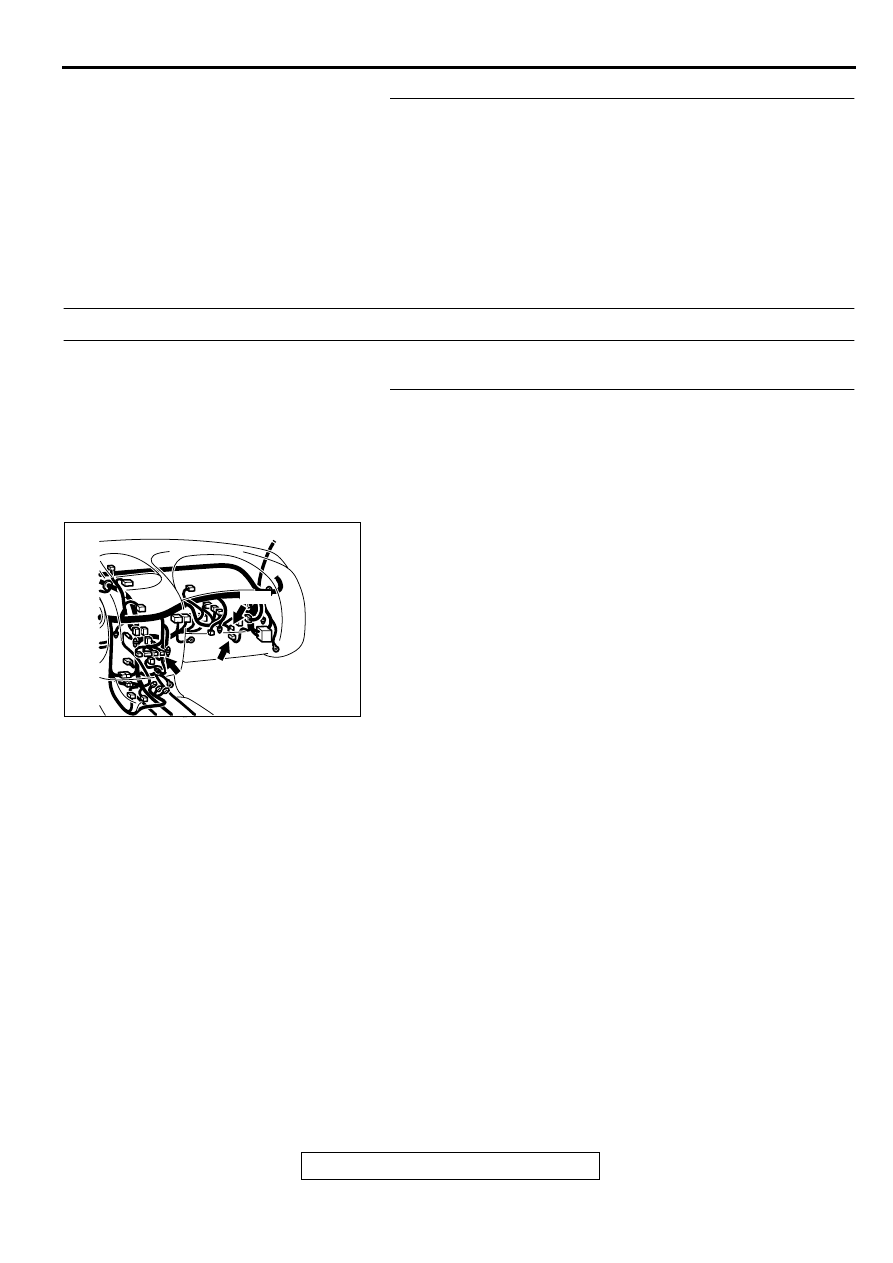
STEP 1. Check the harness wire between the blower fan 
and motor connector C-20, the resistor connector C-19, 
and the blower switch connector C-127.

Q: Is the harness wire between the blower fan and motor 

connector C-20, the resistor connector C-19, and the 
blower switch connector C-127 in good condition?
YES : 
Go to Step 2.
NO :  Repair it. Then go to Step 4.

AC002282

C-20

C-127

C-19

CONNECTORS: C-19, C-20, C-127

AB

MANUAL A/C DIAGNOSIS

TSB Revision

HEATING AND AIR CONDITIONING

55-14

STEP 2. Check the blower relay continuity.

Q: Is the blower relay continuity in good condition?

YES : Go to Step 3.
NO :  Replace. Then go to Step 4.

STEP 3. Check the blower switch continuity.

Q: Is the blower switch continuity in good condition?

YES : Go to Step 4.
NO :  Replace. Then go to Step 4.

STEP 4. Check symptoms.

Q: Does the blower motor stop turning?

YES : This diagnosis is complete. (If no malfunctions are not 

found in all steps, an intermittent malfunction is 
suspected. Refer to GROUP 00E, How to Use 
Troubleshooting/Inspection Service Points 

 How to 

Cope with Intermittent Malfunction 

P.00-6

.)

NO :  Go to Step 1.

BATTERY 
VOLTAGE

TERMINAL NO. 
TO BE 
CONNECTED TO 
BATTERY 

TERMINAL NO. 
TO BE 
CONDUCTED

SUPPLIED

1-3

2-5

NOT SUPPLIED

-

1-3

AC001380

BLOWER RELAY

JUNCTION BLOCK

AB

SWITCH 
POSITION

TESTER 
CONNECTION
(CONNECTOR A) 

SPECIFIED 
CONDITION

0 (OFF)

-

Open circuit

1 (LO)

3-5

Less than two ohm

2 (ML)

1-3

Less than two ohm

3 (MH)

3-6

Less than two ohm

4 (HI)

3-4

Less than two ohm

AC001381AB

BLOWER SWITCH
ASSEMBLY

MANUAL A/C DIAGNOSIS

TSB Revision

HEATING AND AIR CONDITIONING

55-15

INSPACTION PROCEDURE 6: When the A/C is operating condenser fan or radiator fan does not turn.

DIAGNOSIS

STEP 1. Check the fan control relay continuity.

Q: Is the fan control relay continuity in good condition?

YES : Go to Step 2.
NO :  Replace. Then go to Step 4.

STEP 2. Check the condenser fan motor operation 
<vehicles with 3.0L engine>.
Check to be sure that the condenser fan motor operates when 
battery voltage is applied to terminal 2 and terminal 1 
grounded.

Q: Is the condenser fan motor operating correctly?

YES : Go to Step 3.
NO :  Replace. Then go to Step 3.

STEP 3. Measure the fan controller terminal voltage.
Refer to GROUP 14, On-vehicle Service 

 Fan Control Module 

Check 

P.14-18

.

Q: Is the fan controller terminal voltage in good condition?

YES : Go to Step 4.
NO :  Replace. Then go to Step 4.

BATTERY 
VOLTAGE

TERMINAL NO. 
TO BE 
CONNECTED TO 
BATTERY 

TERMINAL NO. 
TO BE 
CONDUCTED

SUPPLIED

1-3

2-5

NOT SUPPLIED

-

1-3

AC001382

FAN CONTROL RELAY

AB

AC001383AB

MANUAL A/C DIAGNOSIS

TSB Revision

HEATING AND AIR CONDITIONING

55-16

STEP 4. Check symptoms.

NOTE: Condenser fan might not operate when there is an air 
conditioning low load from the air conditioning condenser 
control, so remove the negative battery terminal and then 
check the symptoms after 5 minutes since initial start control 
after reconnecting.

Q: Is the condenser fan or radiator fan operating correctly?

YES : This diagnosis is complete. (If no malfunctions are not 

found in all steps, an intermittent malfunction is 
suspected. Refer to GROUP 00E, How to Use 
Troubleshooting/Inspection Service Points 

 How to 

Cope with Intermittent Malfunction 

P.00-6

.)

NO :  Go to Step 1.

INSPACTION PROCEDURE 7: The A/C indicator flashes <vehicles with 3.0L ENGINE> .

THE A/C INDICATOR FLASHES.

STEP 1. Check the drive belt tension.
Refer to GROUP 00, Lubrication and Maintenance Service 


Drive belts.

Q: Is the drive belt tension in good condition?

YES : Go to Step 2.
NO :  Repair. Then go to Step 4.

STEP 2. Check the revolution pick-up sensor.
Measure the resistance between terminals 1 and 3. Check that 
the measured value is at the standard value.

Standard value: 405 

±

 35 

 when the ambient 

temperature is 20 

°

C (68 

°

F

)

Q: Is the measured value at the standard value?

YES : Go to Step 3.
NO :  Replace. Then go to Step 3.

AC003633

1 2

3 4

AB

REVOLUTION 
PICK-UP SENSOR


Content   ..  692  693  694  695   ..