Mitsubishi Eclipse / Eclipse Spyder (2000-2002). Service and repair manual - part 360
 

  Index      Mitsubishi     Mitsubishi Eclipse / Eclipse Spyder (2000-2002). Service and repair manual


Search            


Content   ..  358  359  360  361   ..


Mitsubishi Eclipse / Eclipse Spyder (2000-2002). Service and repair manual - part 360


CHARGING SYSTEM

TSB Revision

ENGINE ELECTRICAL

16-17

DISASSEMBLY SERVICE POINTS

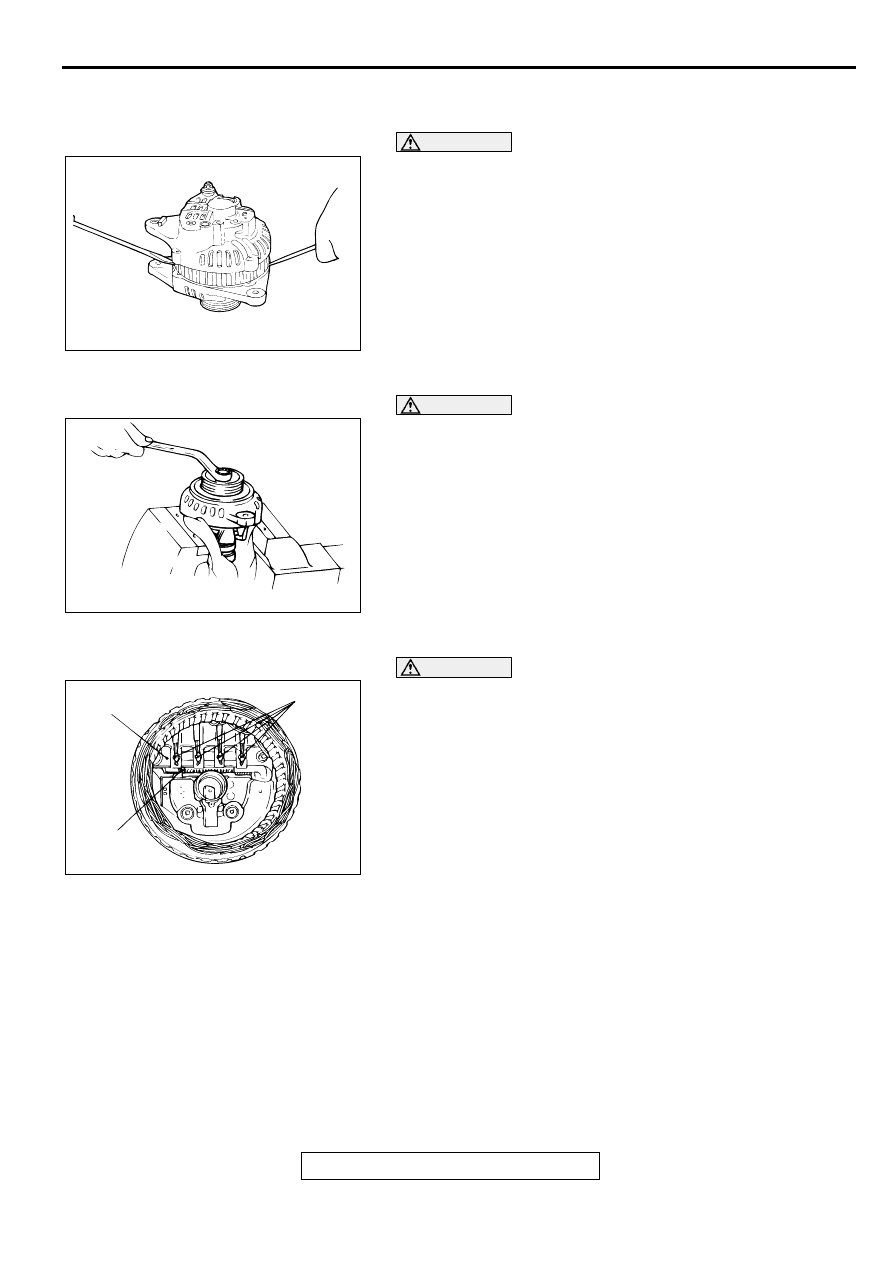
<<A>> FRONT BRACKET ASSEMBLY REMOVAL

CAUTION

Do not insert a screwdriver too deep. The stator coil will be 
damaged.
Insert a flat-tipped screwdriver between the front bracket 
assembly and the stator core, and pry it downward to separate 
the stator and front bracket assembly.

<<B>> GENERATOR PULLEY REMOVAL

CAUTION

Make sure not to damage the rotor.
Set the pulley upward, clamp the rotor in a vise, and remove 
the pulley.

<<C>> STATOR REMOVAL

CAUTION

Check that the heat from the soldering iron is not 
transmitted to the diode for a long time.

Use care that no undue force is exerted to leads of 
diodes.

1. Use a soldering iron (180 to 250 W) to unsolder the stator. 

This work should complete within approximately four 
seconds to prevent heat from transferring to the diode.

2. When removing the rectifier from the regulator assembly, 

unsolder the points soldered on the rectifier.

AKX00355

AKX00356

AKX00357AB

RECTIFIER

SOLDERED

SOLDERED

CHARGING SYSTEM

TSB Revision

ENGINE ELECTRICAL

16-18

ASSEMBLY SERVICE POINTS

>>A<< REGULATOR ASSEMBLY INSTALLATION
After installing the regulator assembly, insert a wire through the 
hole provided on the rear bracket while pressing down on the 
brush, and secure the brush.

NOTE: By inserting a wire, the brush will be secured in place, 
and the installation of the rotor will be easier.

>>B<< ROTOR ASSEMBLY INSTALLATION
After installing the rotor, remove the wire used to secure the 
brush.

INSPECTION

M1161001700022

ROTOR CHECK
1. Check the continuity between the slip rings of the field coil. If 

the resistance value is not within the standard value, replace 
the rotor.

Standard value: approximately 2 

 5 

AKX00358

WIRE

REAR BRACKET

BRUSH

WIRE

AB

AKX00359

WIRE

AB

AKX00360

CHARGING SYSTEM

TSB Revision

ENGINE ELECTRICAL

16-19

2. Check the continuity between the slip ring and the core. If 

there is continuity, replace the rotor.

STATOR CHECK
1. Check the continuity between the coil lead. If there is no 

continuity, replace the stator.

2. Check the continuity between the coil and the core. If there 

is continuity, replace the stator.

RECTIFIER CHECK
1. A positive rectifier test checks the continuity between the 

positive rectifier and the stator coil lead connection terminal 
with a tester. If there is continuity at both terminals, the diode 
is shorted, so replace the rectifier.

AKX00361

AKX00362

AKX00363

AKX00364

CHARGING SYSTEM

TSB Revision

ENGINE ELECTRICAL

16-20

2. A negative rectifier test checks the continuity between the 

negative rectifier and the stator coil lead connection terminal 
with a tester. If there is continuity in both terminals, the diode 
is grounded, so replace the rectifier.

3. A diode trio test checks the continuity of the three diodes by 

connecting an ohmmeter to both ends of each diode. If there 
is continuity in both directions, or if there is no continuity, the 
diode is damaged, so replace the rectifier.

BRUSH CHECK
1. Replace the brush if the brush protrusion length shown in 

the illustration is below the minimum limit value.

Minimum limit:2 mm (0.08 inch)

2. The brush can be removed by unsoldering the brush lead 

wire.

3. When installing a new brush, push the brush in the brush 

holder as shown in the illustration, and solder the lead wire.

AKX00365

AKX00366

AKX00367AB

PROTRU-
SION
LENGTH

AKX00368

SOLDERED

AB


Content   ..  358  359  360  361   ..