Mitsubishi Eclipse. Technical Information Manual (1994) - part 27
 

  Index      Mitsubishi     Mitsubishi Eclipse. Technical Information Manual (1994)


Search            


Content   ..  25  26  27  28   ..


Mitsubishi Eclipse. Technical Information Manual (1994) - part 27


ENGINE <TURBO>

 Emission Control System

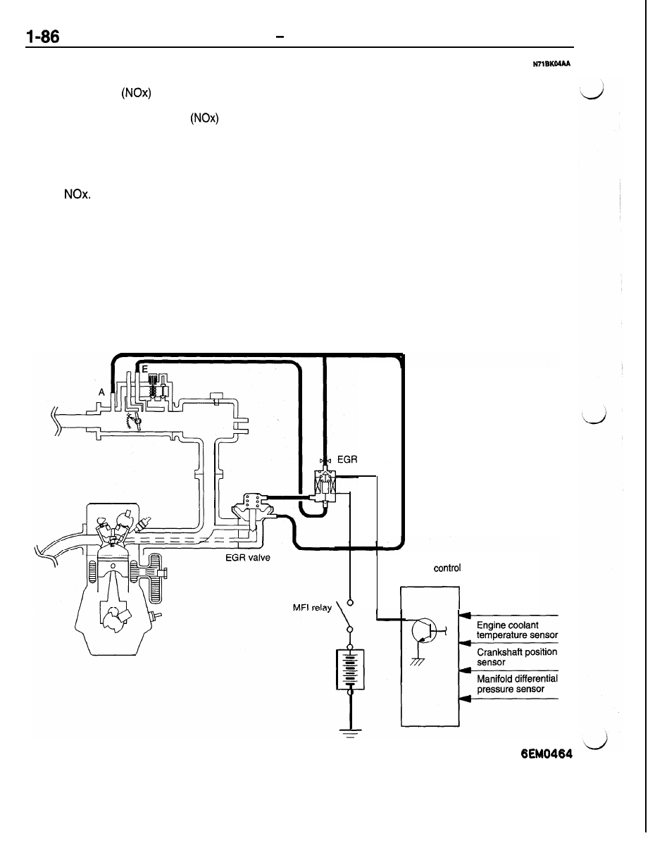
EXHAUST GAS RECIRCULATION (EGR) SYSTEM

The exhaust gas recirculation (EGR) system lowers
the nitrogen oxide 

 emission level. When the

air/fuel mixture combustion temperature is high, a
large quantity of nitrogen oxides 

 is generated

in the combustion chamber. Therefore, this system
recirculates part of emission gas from the exhaust
port of the cylinder head to the combustion chamber

through the intake manifold to decrease the air/fuel

mixture combustion temperature, resulting in reduc-

tion of 

OPERATION
When the engine coolant temperature is low, when
the engine is at idle or when a wide open throttle
operation is performed, the EGR valve is kept
closed, achieving no EGR.

In normal vehicle operation performed after warming
up of the engine, the EGR valve is opened to carry

out EGR.

The EGR flow rate is controlled by the EGR valve

so as not to decrease the driveability.

The EGR system contents:

EGR valve

EGR solenoid

Connecting hoses

The engine control module checks the operation
of the EGR system and, if a trouble is detected,

lights the Check Engine/Malfunction indicator lamp

to warn the driver of the trouble.

solenoid

Engine 
module

  s e n s o r

Volume air flow

ENGINE <TURBO> 

 Mount

I-87

MOUNT


The mounts are basically the same as used on

engine and transaxle is reversed from that on 420A

420A engine except that the arrangement of the

engine.

Crossmember

FRONT

Centermember

Dynamic
damper

Engine
mount

Dynamic
damper

Engine
mount

Transaxle

mount

stopper

Centermember


ENGINE <TURBO> 

 Acceleration System


ACCELERATOR PEDAL AND ACCELERATOR CABLE

The accelerator pedal and accelerator cable are
the same as used on 420A engine. (Refer to 

AUTO-CRUISE CONTROL SYSTEM

By using the auto-cruise control, the driver can drive

at the speed he likes [in a range of approximately
40 to 200 km/h (25 to 124 mph)] without depressing
the accelerator pedal.

CONTROL SYSTEM
The throttle position sensor signal is used in addition
to the conventional vehicle speed sensor as the
input signal to bring about the following improve-
ments in control.
(1) The amount of actuator control varies according

to vehicle speed and throttle opening not only

System Block Diagram

<Control system>

I

Main switch

Throttle position
sensor

I

Closed throttle
position switch

for an expansion of conformity to differences
in engine output but also for better response.

(2) On A/T models, overdrive is released 


 when climbing inclines and the sys-

tem judges the return time by vehicle speed
and throttle opening to prevent hunting between

 and 

ACTUATOR SYSTEM
The actuator system consists of the motor-driven
vacuum pump, actuator and intermediate link. The
vacuum pump and actuator are in different locations.

Vehicle speed

sensor

OD switch

I

I

Control switch

SET switch

RESUME

switch

CANCEL

switch

Control unit

-

-

-

- -

-

-

-

-

-

-

-

-

-

<Actuator system>

Vacuum pump assembly

Diagnostic output
terminal

r - - - -

- - - - - - -

I

Cancel system


I

Stop light switch

I

I

I

I

I

C l u t c h

I

 pedal

Neutral 

 position

position I

 switch

switch 

, <M/T>

I

L - - - - - - - - - . - - - J


  c o n t r o l  

Auto-cruise control indicator light
(in combination meter)

ENGINE <TURBO>   Acceleration System

Components and Functions


sensor

sensor

Auto-cruise control indicator light


Content   ..  25  26  27  28   ..