Mitsubishi Eclipse. Technical Information Manual (1994) - part 17
Long term memory also has control over pulse width
by being able to increase or decrease the pulse
width stored in the cell by up to 25%. Long term
memory is retained by the battery in the PCM, while
short term correction is lost whenever the ignition
is turned off.
The long term memory works to bring the short
term correction to the point where the average
1-46
ENGINE
Control System
cent of pulse width compensation it provides in this
memory cell is 0%. The long term memory returns
to this level of pulse width compensation the next
the vehicle enters this cell. It is in this way
that the PCM is continually relearning the most ap-
propriate level of control, even as the vehicle ages,
internal engine components wear, and operating
conditions change.
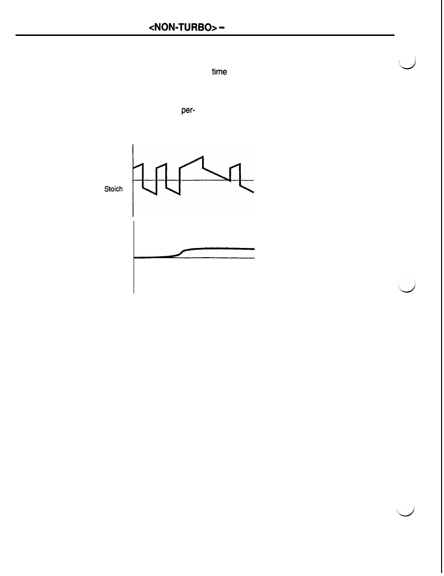
Short term fuel
compensation
A/F ratio
Long term fuel
compensation
There are several “purge free” cells. These cells
contain information on how much effect the canister
has on the air/fuel ratio. The purge solenoid is turned
on to shut off the purge flow and the cell is allowed
to register any purge corruption. The monitor looks
at the combination of short and long term fuel control
values to see if the system is in control.
The fuel system is continuously monitored during
each trip once the enabling conditions have been
AFUO094
met. Short term and long term values are multiplied
together. The test fails if the fuel control system
reduces pulse width by 25% long term memory and
7% short term compensation due to a rich condition
or increases pulse width by 25% long term memory
and 12% short term compensation due to a lean
condition.