Mitsubishi Colt Ralliart. Manual - part 727
 

  Index      Mitsubishi     Mitsubishi Colt Ralliart - service repair manual


Search            


Content   ..  725  726  727  728   ..


Mitsubishi Colt Ralliart. Manual - part 727


TROUBLESHOOTING

MULTIPORT FUEL INJECTION (MPI) <4G1>

13B-233

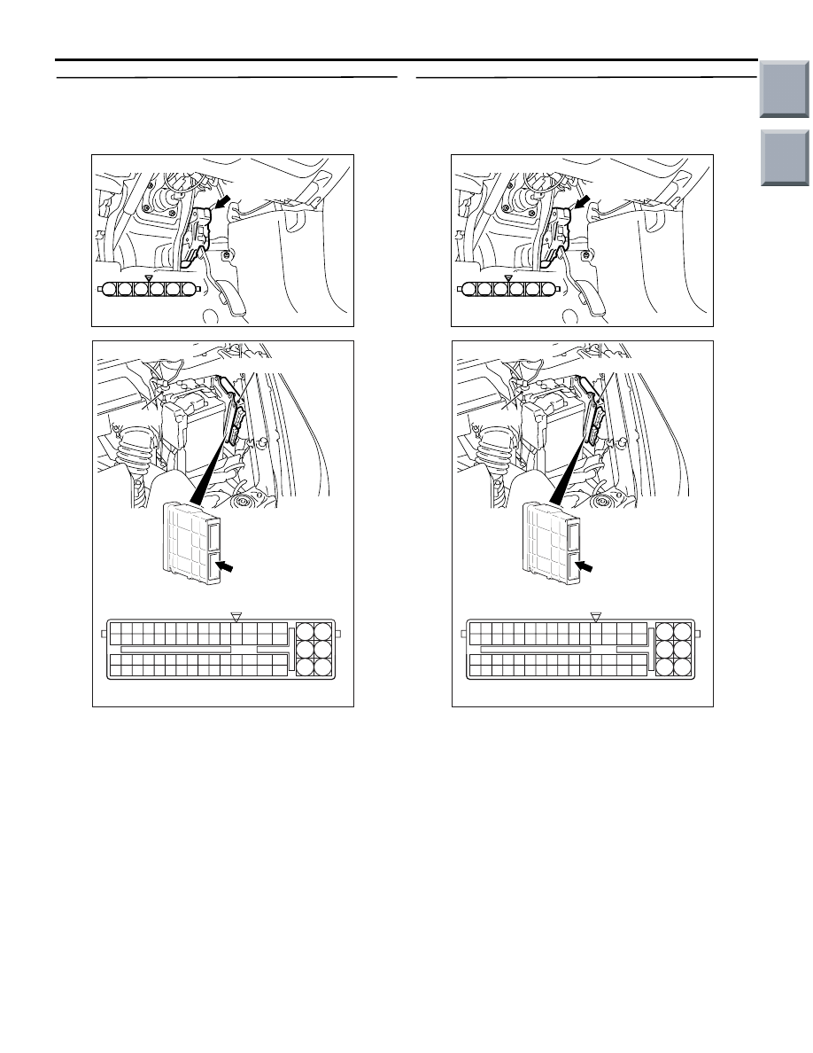
STEP 11. Check harness between B-26 (terminal 
No. 4) accelerator pedal position sensor 
connector and A-08 (terminal No. 86) engine-ECU 
connector.

• Check power supply line for damage.

Q: Is the check result normal?

YES : 

Go to Step 12 .

NO : 

Repair.

STEP 12. Check harness between B-26 (terminal 
No. 3) accelerator pedal position sensor 
connector and A-08 (terminal No. 83) engine-ECU 
connector.

• Check output line for damage.

Q: Is the check result normal?

YES : 

Go to Step 13 .

NO : 

Repair.

AK402092

1

6 5 4 3 2

B-26(B)

AC

Connector: B-26

Harness side 
connector

AK402725

77

78

79

80

81

82

83

84

92

93

94

95

96

97

98

99

85

86

87

88

89

90

91

100

101

102

103

104

105

106

115

116

117

118

119

120

121

107

108

109

110

111

112

113

114

130

131

132

133

134

135

136

122

123

124

125

126

127

128

129

72 71

74 73

76 75

R

AI

A-08

Connector: 

A-08

A-08 Special tool power plant ECU check 
harness

Engine-ECU

Battery

AK402092

1

6 5 4 3 2

B-26(B)

AC

Connector: B-26

Harness side 
connector

AK402725

77

78

79

80

81

82

83

84

92

93

94

95

96

97

98

99

85

86

87

88

89

90

91

100

101

102

103

104

105

106

115

116

117

118

119

120

121

107

108

109

110

111

112

113

114

130

131

132

133

134

135

136

122

123

124

125

126

127

128

129

72 71

74 73

76 75

R

AI

A-08

Connector: 

A-08

A-08 Special tool power plant ECU check 
harness

Engine-ECU

Battery

Main

Index

Group

TOC

TROUBLESHOOTING

MULTIPORT FUEL INJECTION (MPI) <4G1>

13B-234

STEP 13. Check harness between B-26 (terminal 
No. 6) accelerator pedal position sensor 
connector and A-08 (terminal No. 88) engine-ECU 
connector.

• Check output line for damage.

Q: Is the check result normal?

YES : 

Go to Step 14 .

NO : 

Repair.

STEP 14. Replace the accelerator pedal assembly

• After replacing the accelerator pedal assembly, 

re-check the trouble symptoms.

Q: Is the check result normal?

YES : 

Check end.

NO : 

Replace  engine-ECU.

AK402092

1

6 5 4 3 2

B-26(B)

AC

Connector: B-26

Harness side 
connector

AK402725

77

78

79

80

81

82

83

84

92

93

94

95

96

97

98

99

85

86

87

88

89

90

91

100

101

102

103

104

105

106

115

116

117

118

119

120

121

107

108

109

110

111

112

113

114

130

131

132

133

134

135

136

122

123

124

125

126

127

128

129

72 71

74 73

76 75

R

AI

A-08

Connector: 

A-08

A-08 Special tool power plant ECU check 
harness

Engine-ECU

Battery

Main

Index

Group

TOC

TROUBLESHOOTING

MULTIPORT FUEL INJECTION (MPI) <4G1>

13B-235

Code No. U1073: Bus Off

CAUTION

Perform CAN bus-line diagnosis whenever the 
diagnosis code U1073 is set in the engine-ECU.

CAUTION

Replace the ECU only after confirming that the 
communication circuits are normal.

TROUBLE JUDGEMENT

Check Condition

• Ignition switch is in "ON" position.

Judgement Criterion

• When bus off error is detected.

COMMENT ON TROUBLE SYMPTOM

• Most possible causes are defects in CAN bus-line 

harnesses and connectors and malfunction of the 
engine-ECU.

PROBABLE CAUSES

• Failed harnesses and connectors

• Failed engine-ECU

DIAGNOSIS PROCEDURE

STEP 1. M.U.T.-III CAN bus diagnosis

• Using the M.U.T.-III, perform CAN busline diag-

nosis.

Q: Is the check result normal?

YES : 

Go to Step 2.

NO : 

Correct CAN busline (Refer to GROUP 54D 
− Troubleshooting − Can Bus Diagnosis 
Table 

P.54D-13

). After repairing the CAN 

busline, go to Step 3.

STEP 2. M.U.T.-III diagnosis code

• Reconfirm whether the diagnosis code is output 

from engine-ECU.

1. Erase the diagnosis code being output.
2. Ignition switch: LOCK (OFF) to ON
3. Confirm whether the diagnosis code is output.

Q: Is the diagnosis code output?

YES : 

Replace engine-ECU, and then go to Step 

3.

NO : 

Intermittent malfunction (Refer to GROUP 
00 

− How to Use 

Troubleshooting/Inspection Service Points 

− 

How to Cope with Intermittent Malfunctions 

P.00-13

).

STEP 3. M.U.T.-III diagnosis code

• Reconfirm whether the diagnosis code is output 

from engine-ECU.

1. Erase the diagnosis code being output.
2. Ignition switch: LOCK (OFF) to ON
3. Confirm whether the diagnosis code is output.

Q: Is the diagnosis code output?

YES : 

Go to Step 1.

NO : 

Check end.

Main

Index

Group

TOC

TROUBLESHOOTING

MULTIPORT FUEL INJECTION (MPI) <4G1>

13B-236

Code No. U1102: ABS-ECU Time-out

CAUTION

Perform CAN bus-line diagnosis whenever the 
diagnosis code U1102 is set in the engine-ECU.

CAUTION

Replace the ECU only after confirming that the 
communication circuits are normal.

TROUBLE JUDGEMENT

Check Conditions

• Ignition switch is in "ON" position.

• Battery voltage is more than 10 V.

• Cranking switch is in the OFF position or 3 sec-

onds after turning the cranking switch from ON to 
OFF.

Judgement Criterion

• Signals from the ABS-ECU via the CAN bus-line 

cannot be received.

COMMENTS ON TROBLE SYMPTOMS

Current malfunction

• Most possible malfunctions are defects in CAN 

bus-line harnesses and connectors between the 
engine-ECU and ABS-ECU, malfunction in the 
ABS-ECU power supply system, or malfunction 
of the ABS-ECU or engine-ECU.

Past malfunction

• Focus on diagnosing malfunction of the harness 

and connector in CAN busline between 
engine-ECU and ABS-ECU as well as malfunc-
tion in the power supply system of ABS-ECU 
(Refer to GROUP 00 

− How to use Troubleshoot-

ing/Inspection Service Points 

− How to Cope with 

Intermittent Malfunctions 

P.00-13

).

NOTE: In case of Past malfunction, M.U.T.-III CAN 

bus diagnosis cannot detect the failure even if 
there is malfunction in CAN bus, so that check 
CAN busline in the same way as Intermittent mal-
function (Refer to GROUP 00 

 How to use Trou-

bleshooting/Inspection Service Points 

 How to 

Cope with Intermittent Malfunctions 

P.00-13

). 

The diagnosis codes being output to each ECU 
with CAN communication can narrow down the 
most suspected area. (Refer to GROUP 54D 


Troubleshooting 

 CAN Bus Diagnosis Table 

P.54D-13

).

PROBABLE CAUSES

• Failed harnesses and connectors in the CAN 

busline

• Failed ABS-ECU

• Failed engine-ECU

DIAGNOSIS PROCEDURE

STEP 1. M.U.T.-III CAN bus diagnosis

• Using M.U.T.-III, perform CAN busline diagnosis.

Q: Is the check result normal?

YES : 

Go to Step 2.

NO : 

Repair the CAN busline (Refer to GROUP 
54D 

− Troubleshooting − CAN Bus 

Diagnosis Table 

P.54D-13

). After repairing 

the CAN busline, go to Step 6.

STEP 2. M.U.T.-III other system diagnosis codes

• Confirm whether diagnosis codes are output from 

ABS-ECU.

Q: Is the diagnosis code output?

YES : 

Perform the troubleshooting of ABS. (Refer 

to GROUP 35B 

− Troubleshooting − Check 

Chart for Diagnosis Code 

P.35B-7

).

NO : 

Go to Step 3.

STEP 3. M.U.T.-III other system diagnosis codes
Check whether the diagnosis code U1102: ABS-ECU 
time-out is output from the following ECU having 
CAN communication with ABS-ECU.

• EPS-ECU

• Meter-A/C-ECU

Q: Is the diagnosis code output?

YES : 

Go to Step 4.

NO : 

Go to Step 5.

STEP 4. M.U.T.-III diagnosis code

• Reconfirm whether the diagnosis code is output 

engine-ECU.

1. Erase the diagnosis code being output.
2. Ignition switch: LOCK (OFF) to ON
3. Confirm whether the diagnosis code is output.

Q: Is the diagnosis code output?

YES : 

Replace ABS-ECU, and then go to Step 6.

NO : 

Intermittent malfunction in the CAN busline 
between the engine-ECU and ABS-ECU 
(Refer to GROUP 00 

− How to Cope with 

Intermittent Malfunctions 

P.00-13

).

Main

Index

Group

TOC


Content   ..  725  726  727  728   ..