Mitsubishi Colt Ralliart. Manual - part 525
 

  Index      Mitsubishi     Mitsubishi Colt Ralliart - service repair manual


Search            


Content   ..  523  524  525  526   ..


Mitsubishi Colt Ralliart. Manual - part 525


TROUBLESHOOTING

HEATER, AIR CONDITIONER AND VENTILATION

55A-8

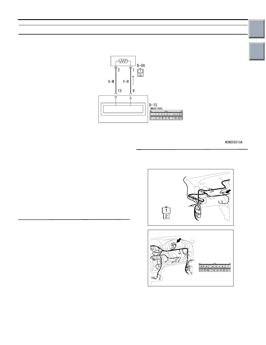
Code No. B1021,B1022: Air thermo sensor system

AIR THERMO
SENSOR

COMBINATION
METER

Wire colour code
B : Black     LG : Light green     G : Green     L : Blue     W : White     Y : Yellow     SB : Sky blue
BR : Brown     O : Orange     GR : Gray     R : Red     P : Pink     V : Violet

SENSOR CIRCUIT

METER AND A/C-ECU

Air Thermo Sensor Circuit

DIAGNOSIS CODE SET CONDITION

This code is set when the air thermo sensor circuit is 
open (Code No.B1022) or is short (Code No.B1021).

POSSIBLE CAUSES

• Malfunction of the air thermo sensor

• Damaged the wiring harness or connectors

• Malfunction of the combination meter (meter and 

A/C-ECU)

DIAGNOSIS PROCEDURE

Step 1. M.U.T.-III data list
Check that the following service data display con-
tents are normal. (Refer to 

P.55A-44

.)

• Item 03: Air thermo sensor

Q: Is the check result normal?

YES : 

Go to Step 5.

NO : 

Go to Step 2.

Step 2. Connector check: B-15 combination 
meter connector and B-08 air thermo sensor 
connector

AC401053

Connector: B-08

AE

Harness side

AC401055

AE

Connector: B-15

B-15 (B)

Harness side

Q: Is the check result normal?

YES : 

Go to Step 3.

NO : 

Repair the connector.

Main

Index

Group

TOC

TROUBLESHOOTING

HEATER, AIR CONDITIONER AND VENTILATION

55A-9

Step 3. Check the wiring harness between B-15 
combination meter connector (terminals 9 and 
15) and B-08 air thermo sensor connector 
(terminals 1 and 2).

AC401053

Connector: B-08

AE

Harness side

AC401055

AE

Connector: B-15

B-15 (B)

Harness side

• Check the sensor signal line and earth line for 

open or short circuit.

Q: Is the check result normal?

YES : 

Go to Step 4.

NO : 

Repair the wiring harness.

Step 4. Check the air thermo sensor.
Refer to 

P.55A-59

.

Q: Is the check result normal?

YES : 

Go to Step 5.

NO : 

Replace the air thermo sensor.

Step 5. Check whether the diagnosis code is 
reset.

Q: Is the diagnosis code set?

YES : 

Replace the combination meter (meter and 

A/C-ECU).

NO : 

The trouble can be an intermittent 
malfunction (Refer to GROUP 00, How to 
Cope with Intermittent Malfunction 

P.00-13

).

Code No. B1082 Automatic/manual types abnormal error

DIAGNOSIS CODE SET CONDITION

This diagnosis code is set when the heater control 
specification does not meet the combination meter 
(meter and A/C-ECU) specification.

POSSIBLE CAUSES

• Malfunction of the heater control assembly

• Malfunction of the combination meter (meter and 

A/C-ECU)

DIAGNOSIS PROCEDURE

STEP 1. Replace the heater control

Q: Is the check result normal?

YES : 

This diagnosis is complete.

NO : 

Replace the combination meter (meter and 
A/C-ECU).

Main

Index

Group

TOC

TROUBLESHOOTING

HEATER, AIR CONDITIONER AND VENTILATION

55A-10

TROUBLE SYMPTOM CHART

M1554005000388

Trouble symptom

Inspection procedure 
number

Reference page

Communication with the M.U.T.-III is not possible

1

P.55A-10

The air conditioner does not work at all.

2

Cool air does not come

3

P.55A-11

The blower does not work

4

P.55A-15

The blower air volume cannot be changed

5

P.55A-21

The inside/outside air changeover is impossible

6

P.55A-24

The A/C compressor does not work

7

P.55A-27

The rear window defogger does not work

8

P.55A-32

The A/C indicator flashes

9

P.55A-38

A/C pressure sensor system

10

P.55A-41

SYMPTOM PROCEDURES

Inspection Procedure 1: Communication with the M.U.T.-III is not possible


Inspection Procedure 2: The air conditioner does not work at all.

COMMENTS ON TROUBLE SYMPTOM

If communication with all other systems is not possi-
ble, there is a high possibility that there is a malfunc-
tion of the diagnosis line. If only the A/C system can 
not communicate with the M.U.T.-III, the combination 
meter (meter and A/C-ECU) may be defective.

POSSIBLE CAUSE

Malfunction of the combination meter (meter and 
A/C-ECU) 

DIAGNOSIS PROCEDURE

Step 1. Check the communication with 
combination meter 

Q: Can the M.U.T.-III communicate with the 

combination meter?
YES : 

Inspection Procedure 3: Cool air does not 

come 

P.55A-11

NO : 

Diagnose the combination meter. Refer to 

P.54A-42

.

Main

Index

Group

TOC

TROUBLESHOOTING

HEATER, AIR CONDITIONER AND VENTILATION

55A-11

Inspection Procedure 3: Cool air does not come

BLOWER
RELAY

BLOWER
SWITCH

COMBINATION
METER

A/C CONTROL CIRCUIT

METER AND
A/C-ECU

HEATER
CONTROL
ASSEMBLY

A/C
SWITCH

POWER
SOURCE

Wire colour code
B : Black     LG : Light green     G : Green     L : Blue     W : White     Y : Yellow     SB : Sky blue
BR : Brown     O : Orange     GR : Gray     R : Red     P : Pink     V : Violet

Blower switch and  Heater Control Assembly Circuit

CIRCUIT OPERATION

If the blower air temperature can not be cool when 
turning A/C switch ON and lowering the preset tem-
perature, inadequate refrigerant quantity, sensors, 
harness or connectors may be suspected.

POSSIBLE CAUSES

Damaged the wiring harness or connectors

DIAGNOSIS PROCEDURE

Step 1. M.U.T.-III CAN bus diagnostics
Use the M.U.T.-III to diagnose the CAN bus lines.

Q: Is the check result normal?

YES : 

Go to Step 2.

NO : 

Repair the CAN bus lines. (Refer to GROUP 
54D, Troubleshooting 

P.54D-13

.)

Main

Index

Group

TOC


Content   ..  523  524  525  526   ..