Mitsubishi Colt Ralliart. Manual - part 524


  Index      Mitsubishi     Mitsubishi Colt Ralliart - service repair manual


Search            


Content   ..  522  523  524  525   ..


Mitsubishi Colt Ralliart. Manual - part 524


MB991910

MB991826

MB991955

MB991911

MB991824

MB991827

MB991825

A

B

C

D

E

F

DO NOT USE

SPECIAL TOOL

HEATER, AIR CONDITIONER AND VENTILATION

55A-4

MB991955
A: MB991824
B: MB991827
C: MB991910
D: MB991911
E: MB991825
F: MB991826

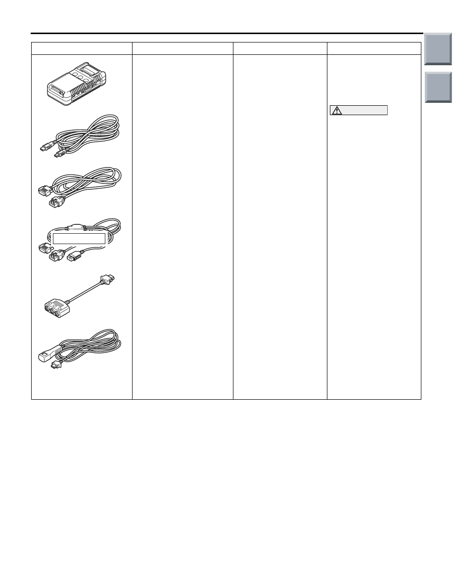
M.U.T.-III sub-assembly
A: Vehicle 
Communication 
Interface (V. C. I.)
B: USB cable
C: M.U.T.-III main 
harness A (applicable to 
vehicles with CAN 
communication)
D: M.U.T.-III main 
harness B (applicable to 
vehicles without CAN 
communication)
E: Measurement adapter
F: Trigger harness

Check the A/C (The 
M.U.T.-III diagnosis 
codes display, service 
data display and 
actuator test)

CAUTION

For vehicles with CAN 
communication, use 
M.U.T.-III main harness 
A to send simulated 
vehicle speed. If you 
connect M.U.T.-III main 
harness B instead, the 
CAN communication 
does not function 
correctly.

Tool

Number

Name

Use

Main

Index

Group

TOC

TROUBLESHOOTING

HEATER, AIR CONDITIONER AND VENTILATION

55A-5

TROUBLESHOOTING

DIAGNOSIS TROUBLESHOOTING FLOW

M1554004700232

Refer to GROUP 00, How to Use Troubleshoot-
ing/Inspection Service Points 

P.00-12

.

DIAGNOSIS FUNCTION

M1554004800251

HOW TO READ DIAGNOSIS CODE

Connect the M.U.T.-III to the 16-pin diagnosis con-
nector to read diagnosis code (Refer to GROUP 00, 
How to Use Troubleshooting/Inspection Service 
Points 

P.00-12

).

HOW TO ERASE DIAGNOSIS CODE

Refer to GROUP 00, How to Use Troubleshoot-
ing/Inspection Service Points 

P.00-12

.

DIAGNOSIS CODE CHART

M1554004900377

Code No.

Diagnostic item

Reference 
page

Service data 
display 
contents when 
diagnosis 
code is set

B1011

Ambient temperature sensor system (short circuit)

P.55A-6

20

°C

B1012

Ambient temperature sensor system (open circuit)

B1021

Air thermo sensor system (short circuit)

P.55A-8

−6°C

B1022

Air thermo sensor system (open circuit)

B1082

Automatic/manual types abnormal error

P.55A-9

U1073

Bus off error

Refer to 
GROUP 54A, 
COMBINATION 
METER 

P.54A-31

U1100

Engine-CVT-ECU time-out

U1101
U1102

ABS-ECU time-out

U1106

EPS-ECU time-out

U1109

ETACS-ECU time-out

U1120

Failure information on engine-CVT-ECU (related to 
engine)

U1206

Flag invalid

Main

Index

Group

TOC

TROUBLESHOOTING

HEATER, AIR CONDITIONER AND VENTILATION

55A-6

DIAGNOSTIC TROUBLE CODE 
PROCEDURES

Code No. B1011,B1012: Ambient temperature sensor system

AMBIENT
TEMPERATURE
SENSOR

COMBINATION
METER

SENSOR CIRCUIT

Wire colour code
B : Black     LG : Light green     G : Green     L : Blue     W : White     Y : Yellow     SB : Sky blue
BR : Brown     O : Orange     GR : Gray     R : Red     P : Pink     V : Violet

METER AND A/C-ECU

Ambient Temperature Sensor Circuit

DIAGNOSIS CODE SET CONDITION

This code is set when the ambient temperature sen-
sor circuit is open (Code No.B1012) or is short (Code 
No.B1011).

POSSIBLE CAUSES

• Malfunction of the ambient temperature sensor

• Damaged the wiring harness and connectors

• Malfunction of the combination meter (meter and 

A/C-ECU)

DIAGNOSIS PROCEDURE

Step 1. M.U.T.-III data list
Check that the following service data display con-
tents are normal. (Refer to 

P.55A-44

.)

• Item 02: Ambient temperature sensor

Q: Is the check result normal?

YES : 

Go to Step 5.

NO : 

Go to Step 2.

Main

Index

Group

TOC

TROUBLESHOOTING

HEATER, AIR CONDITIONER AND VENTILATION

55A-7

Step 2. Connector check: A-19 ambient 
temperature sensor connector and B-15 
combination meter connector

AC313811

Connector: A-19

A-19 (B)

AB

Harness side

AC401055

AE

Connector: B-15

B-15 (B)

Harness side

Q: Is the check result normal?

YES : 

Go to Step 3.

NO : 

Repair the connector.

Step 3. Check the wiring harness between A-19 
ambient temperature sensor connector 
(terminals 1 and 2) and B-15 A/C-ECU connector 
(terminals 15 and 10).

AC313811

Connector: A-19

A-19 (B)

AB

Harness side

AC401055

AE

Connector: B-15

B-15 (B)

Harness side

NOTE: 

AC401053

AD

Connector: B-41

Prior to the wiring harness inspection, check interme-
diate connector B-41, and repair if necessary.

• Check the sensor signal line and earth line for 

open or short circuit.

Q: Is the check result normal?

YES : 

Go to Step 4.

NO : 

Repair the wiring harness.

Step 4. Check the ambient temperature sensor.
Refer to 

P.55A-62

.

Q: Is the check result normal?

YES : 

Go to Step 5.

NO : 

Replace the ambient temperature sensor.

Step 5. Check whether the diagnosis code is 
reset.

Q: Is the diagnosis code set?

YES : 

Replace the combination meter (meter and 

A/C-ECU).

NO : 

The trouble can be an intermittent 
malfunction (Refer to GROUP 00, How to 
Cope with Intermittent Malfunction 

P.00-13

).

Main

Index

Group

TOC


Content   ..  522  523  524  525   ..