Mitsubishi 380. Manual - part 889


  Index      Mitsubishi     Mitsubishi 380 - service repair manual 2005 year


Search            


Content   ..  887  888  889  890   ..


Mitsubishi 380. Manual - part 889


COMBINATION METER ASSEMBLY

CHASSIS ELECTRICAL

54A-90

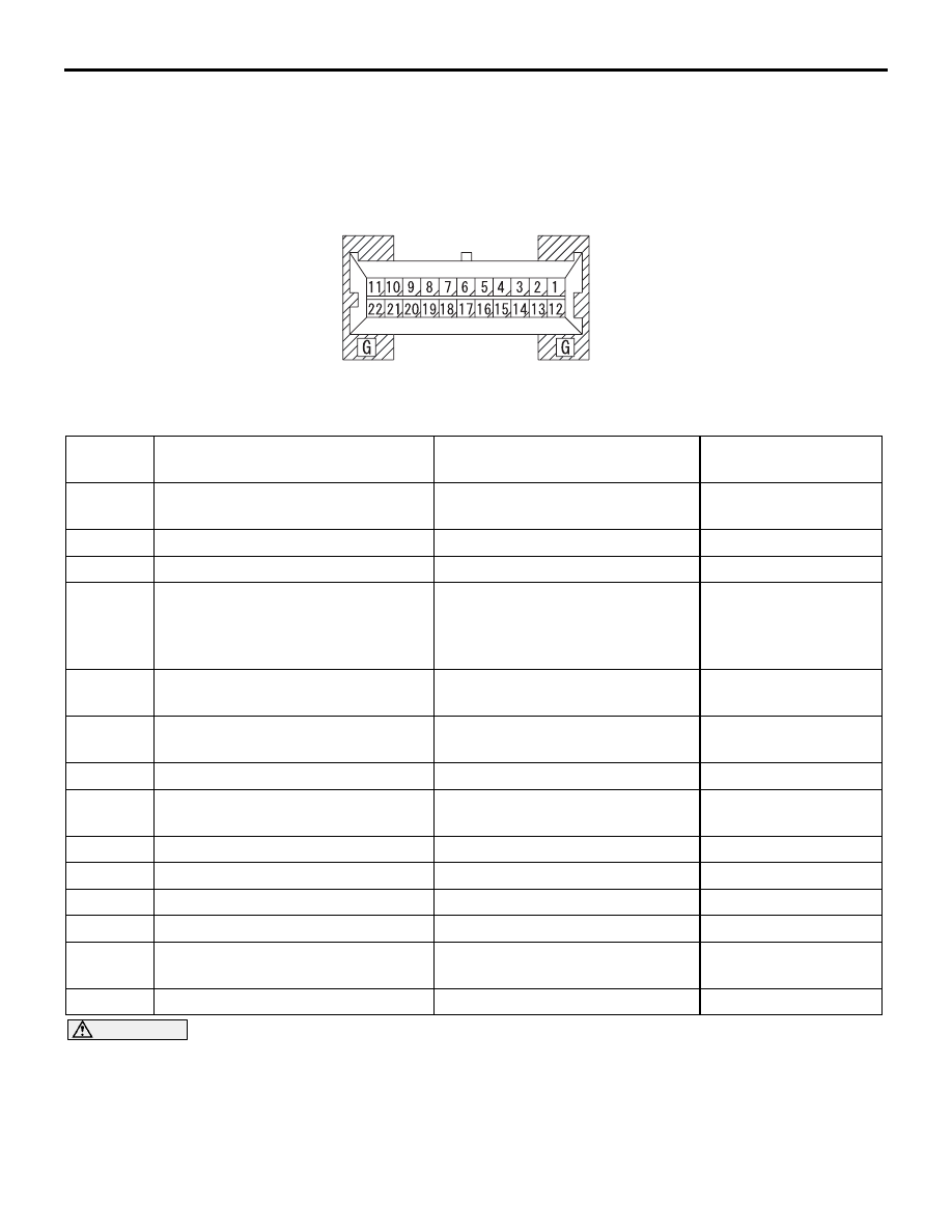
COMBINATION METER TERMINAL CHECK

M1543026700010

Measure the voltage between terminals using a volt-
meter.

NOTE: The combination meter connector is fixed on the instrument panel directly, so you can not take mea-
surement by backprobing.

CAUTION

Never take a measurement at terminals 14 and 
15. If you do this, the CAN bus lines will be 
impaired.

AC211750

COMBINATION METER CONNECTOR
COMPONENT SIDE

AD

C-101

Terminal 
No.

Check item

Check condition

Normal condition

1

Battery power supply

Always

Battery positive 
voltage

3

Gauge ground

Always

0 V

5

Ground

Always

0  V

7

Parking brake switch and brake 
fluid level switch

• Ignition switch: ON or parking 

brake switch: ON

• Ignition switch: ON or brake 

fluid level switch: ON

-

8

Seat belt switch

Ignition switch: ON or driver’s 
seat belt not fastened

-

9

Engine oil pressure switch

Ignition switch: ON or engine oil 
pressure switch: ON

-

11

Alternator (charge circuit)

-

-

12

Ignition switch (IG1) power supply

Ignition switch: ON

Battery positive 
voltage

13

Fuel gauge 

Always

-

16

Mode switch

Always

0 V

17

Mode switch (UP)

Always

0 V

18

Mode switch (DOWN)

Always

0 V

21

Illumination (power supply)

Lighting switch: ON

Battery positive 
voltage

22

Illumination (ground)

Always

0 V

COMBINATION METER ASSEMBLY

CHASSIS ELECTRICAL

54A-91

SPECIAL TOOLS

M1543000601771

TOOL

TOOL NUMBER 
AND NAME

REPLACED BY 
MILLER TOOL 
NUMBER

APPLICATION

MB991958

A: MB991824
B: MB991827
C: MB991910
D: MB991911
E: MB991914
F: MB991825
G: MB991826

MUT-III Sub 
Assembly

A: Vehicle 

communication 
interface (V.C.I.)

B: MUT-III USB cable
C: MUT-III main 

harness A 
(Vehicles with CAN 
communication 
system)

D: MUT-III main 

harness B 
(Vehicles without 
CAN 
communication 
system)

E: MUT-III main 

harness C (for 
Daimler Chrysler 
models only)

F: MUT-III 

measurement 
adapter

G: MUT-III trigger 

harness

MB991824-KIT

NOTE: G: MB991826 
MUT-III Trigger Harness 
is not necessary when 
pushing V.C.I. ENTER 
key.

• Reading diagnostic 

trouble code

• Estimated vehicle 

speed sent

CAUTION

MUT-III main harness A 
(MB991910) should be 
used. MUT-III main 
harness B and C 
should not be used for 
this vehicle.

MB991910

MB991826

MB991958

MB991911

MB991914

MB991824

MB991827

MB991825

DO NOT USE

A

B

C

D

E

F

G

DO NOT USE

COMBINATION METER ASSEMBLY

CHASSIS ELECTRICAL

54A-92

ON-VEHICLE SERVICE

SPEEDOMETER CHECK

M1543000900445

1. Adjust the pressure of tyres to the specified level (Refer to 

GROUP 31, On-vehicle Service 

P.31-7

).

CAUTION

Do not accelerate or decelerate suddenly during servicing 
work.
2. Set the vehicle onto a speedometer tester and use wheel 

chocks to hold the rear wheels.

3. To prevent the front wheel from moving from side to side, 

attach tension bars to the tie-down hook, and secure both 
ends to anchor plates.

4. To prevent the vehicle from moving, attach a chain or wire to 

the rear retraction hook, and make sure the end of the chain 
or wire is secured.

5. Check if the speedometer indicator range is within the 

standard values.

Standard value:

MB991223
A: MB991219
B: MB991220 
C: MB991221
D: MB991222 

Harness set

A: Test harness
B: LED harness
C: LED harness 

adapter

D: Probe

General service tool 
(jumper)

Making voltage and 
resistance 
measurements during 
troubleshooting

A: Connect pin contact 

pressure inspection

B: Power circuit 

inspection

C: Power circuit 

inspection

D: Commercial tester 

connection

TOOL

TOOL NUMBER 
AND NAME

REPLACED BY 
MILLER TOOL 
NUMBER

APPLICATION

MB991223

A

D

C

B

AF

AC001287AB

WHEEL CHOCKS

ACX00775 AB

FRONT

ANCHOR PLATE

PULLER

COMBINATION METER ASSEMBLY

CHASSIS ELECTRICAL

54A-93

6. If not within the standard value, check the tyre size. If an 

incorrect size of tyre is used, replace it and check again. If 
the tyre size is correct, a defect may be present in 
components and circuit between the output shaft speed 
sensor (Automatic transmission) or speed sensor (Manual 
transmission) and the combination meter. Check the 
following items.

• output shaft speed sensor (automatic transmission) (refer to 

GROUP23A, Automatic Transmission Diagnosis 

P.23A-72

).

• vehicle speed sensor (manual transmission (M/T)) refer to 

GROUP 13A, Multiport fuel injection (refer to 

P.13A-399

).

• combination meter (refer to 

P.54A-76

.)

TACHOMETER CHECK

M1543001000456

Required Special Tools:

• MB991958: Diagnostic Tool (MUT-III Sub Assembly)

• MB991824: Vehicle Communication Interface (V.C.I.)

• MB991827: MUT-III USB Cable

• MB991911: MUT-III Main Harness A (Vehicles with CAN 

communication system)

STANDARD 
INDICATION km/h

TOLERANCE   km/h

0

± 1°

20

0   to  +4

40

0   to  +4

80

+0.5  to   +5.5

120

+1.5  to   +7.5

160

+2.5  to   +9.5

200

+3.5  to   +11.5


Content   ..  887  888  889  890   ..