Mitsubishi 380. Manual - part 247


  Index      Mitsubishi     Mitsubishi 380 - service repair manual 2005 year


Search            


Content   ..  245  246  247  248   ..


Mitsubishi 380. Manual - part 247


CHARGING SYSTEM

ENGINE ELECTRICAL

16-10

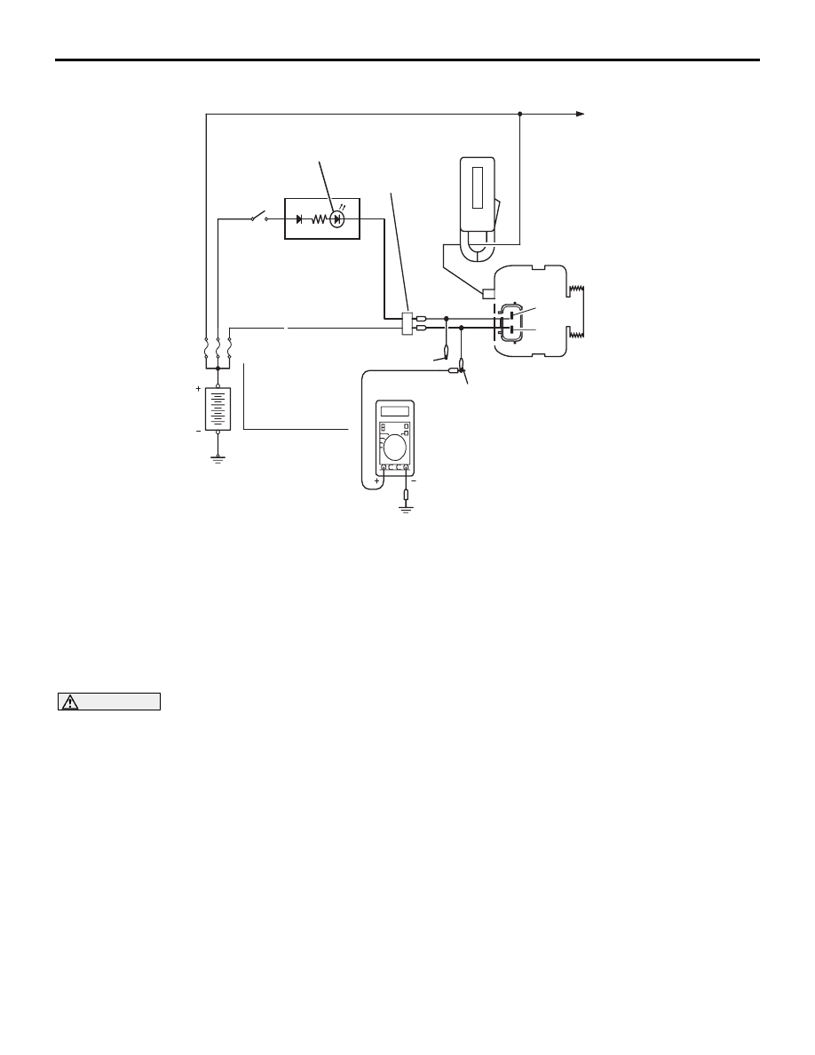
REGULATED VOLTAGE TEST

M1161001100666

Required Special Tools:

• : Diagnostic Tool (MUT-III)

• MB991824: V.C.I.

• MB991827: MUT-III USB Cable

• MB991910: MUT-III Main Harness A

• MB998467: Alternator Harness Connector

This test determines whether the voltage regulator is 
correctly controlling the alternator output voltage.

WARNING

Battery posts, terminals and related acces-
sories contain lead and lead compounds. 
WASH HANDS AFTER HANDLING.

1. Always be sure to check the following before the 

test:

• Alternator installation

• Check to be sure that the battery installed in the 

vehicle is fully charged. (Refer to GROUP 54A, 
Chassis Electrical 

− Battery − On-vehicle Service 

− Battery Check 

P.54A-5

.)

• Alternator drive belt tension (Refer to GROUP 00, 

General 

− Maintenance Service − Drive Belts 

(For Alternator, Power Steering Pump and Air 
Conditioning) (Check) 

P.00-39

.)

• Fusible link

• Abnormal noise from the alternator while the 

engine is running.

2. Turn the ignition switch to the "LOCK" (OFF) 

position.

3. Disconnect the negative battery cable.

4. Use the special tool (Alternator harness 

connector: MB998467) to connect a digital-type 
voltmeter between the alternator "S" terminal and 
ground. (Connect the positive lead of the 
voltmeter to the "S" terminal, and then connect the 
negative lead of the voltmeter to a secure ground 
or to the negative battery terminal.)

5. Connect a clamp-type DC test ammeter with a 

range of 0 

− 120 A to the alternator "B" terminal 

output wire.

6. Reconnect the negative battery cable.

7. Connect an engine tachometer, or diagnostic tool.

8. Turn the ignition switch to the "ON" position and 

check that the reading on the voltmeter is equal to 
the battery positive voltage.

NOTE: If the voltage is 0 V, the cause is probably 
an open circuit in the wire or fusible link between 
the alternator "S" terminal and the battery positive 
terminal or malfunctioning voltmeter.

9. Check to be sure that all lights and accessories 

are off.

10.Start the engine.

06DB025A

BATTERY

IGNITION

SWITCH

AMMETER 

(CLAMP-TYPE)

LOAD

MB998467

VOLTMETER (DIGITAL-TYPE)

RED

YELLOW

ALTERNATOR

B

ALTERNATOR

MALFUNCTION

LIGHT

COMBINATION 

METER

L

S

CHARGING SYSTEM

ENGINE ELECTRICAL

16-11

11.Increase the engine speed to 2,500 r/min.

12.Read the value displayed on the voltmeter when 

the current output by the alternator becomes 10 A 
or less.

13.If the voltage reading conforms to the value in the 

voltage regulation table, then the voltage regulator 
is operating normally.

If the voltage is outside the standard value, there 
is a malfunction of the voltage regulator or the 
alternator (Refer to the following table).

14.After the test, lower the engine speed to idle.

15.Turn the ignition switch to the "LOCK" (OFF) 

position.

16.Disconnect the engine tachometer or diagnostic 

tool .

17.Disconnect the negative battery cable.

18.Disconnect the ammeter and voltmeter.

19.Connect the negative battery cable.

20.Run the engine for 10 minutes at an idle.

VOLTAGE REGULATION TABLE

WAVE PATTERN CHECK USING AN 
OSCILLOSCOPE

M1161001200180

.

MEASUREMENT METHOD

Connect the oscilloscope special patterns pick-up to the 
alternator "B" terminal.

.

STANDARD WAVEFORM

INSPECTION TERMINAL

VOLTAGE REGULATOR 
AMBIENT TEMPERATURE [

°

(

°F)]

STANDARD VALUE (V)

Terminal "S"

−20 (−4)

14.2 

− 15.4

20 (68)

13.9 

− 14.9

60 (140)

13.4 

− 14.5

80 (176)

13.1 

− 14.2

06DB029A

ALTERNATOR

OSCILLOSCOPE

"B" TERMINAL

PROBE

Observation Conditions

FUNCTION

SPECIAL PATTERNS

Pattern height

Variable

Variable knob

Adjust while viewing the wave 
pattern

Pattern selector

Raster

Engine revolutions

Curb idle speed

CHARGING SYSTEM

ENGINE ELECTRICAL

16-12

NOTE: The voltage waveform of the alternator "B" terminal can 
undulate as shown at left. This waveform is produced when the 
regulator operates according to fluctuations in the alternator 
load (current), and is normal for the alternator.
If the ripple height is abnormally high (approximately 2 V or 
more during idling), the wires between the alternator "B" termi-
nal and the battery have broken due to fuse blowing, etc. The 
alternator is usually operating properly.

.

ABNORMAL WAVEFORMS EXAMPLES

NOTE: The size of the waveform patterns can differ greatly, 
depending on the adjustment of the variable knob on the oscil-
loscope.

NOTE:  Identification of abnormal waveforms is easier when 
there is a large output current (regulator is not operating). 
(Waveforms can be observed when the headlights are illumi-
nated.)

NOTE: Check the conditions of the alternator malfunction light 
(illuminated/not illuminated) also, and carry out a total check.

ABNORMAL WAVEFORMS

• Example 1

PROBABLE CAUSE: Open circuit in diode

AKX00189

0.4

(V)

0.2

  0

–0.2

–0.4

VOLTAGE AT
GENERATOR
"B" TERMINAL

TIME

AB

AKX00190

AKX00191

CHARGING SYSTEM

ENGINE ELECTRICAL

16-13

• Example 2

PROBABLE CAUSE: Short-circuit in diode

• Example 3

PROBABLE CAUSE: Open circuit in stator coil

• Example 4

PROBABLE CAUSE: Short-circuit in stator coil

AKX00192

AKX00193

AKX00194


Content   ..  245  246  247  248   ..