Mitsubishi 380. Manual - part 214


  Index      Mitsubishi     Mitsubishi 380 - service repair manual 2005 year


Search            


Content   ..  212  213  214  215   ..


Mitsubishi 380. Manual - part 214


HEATER UNIT, HEATER CORE, BLOWER ASSEMBLY AND EVAPORATOR UNIT

HEATER, AIR CONDITIONING AND VENTILATION

55-152

REMOVAL SERVICE POINTS

.

<<A>> SUCTION PIPE AND LIQUID PIPE DISCON-
NECTION

CAUTION

As the compressor oil and receiver are highly moisture 
absorbent, use a non-porous material to plug the hose and 
nipples.
To prevent the entry of dust or other foreign bodies, plug the 
dismantled hose and the nipples of the expansion valves.

.

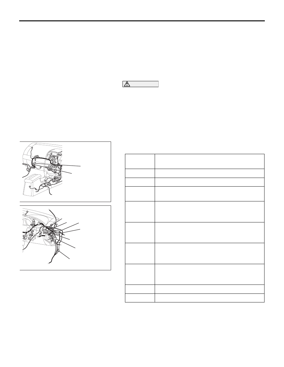
<<B>> HEATER UNIT AND DECK 
CROSSMEMBER ASSEMBLY REMOVAL

Disconnect the following connectors to gain access to the front 
deck crossmember.

6.

ETACS-ECU

<<B>>

7.

HEATER UNIT AND DECK 
CROSSMEMBER ASSEMBLY

REMOVAL STEPS (Continued)

Connector 
number

Connector name

C-113

AUDIO AMPLIFIER

C-114

AUDIO AMPLIFIER

C-25

FRONT WIRING HARNESS AND FLOOR 
WIRING HARNESS COMBINATION

C-26

INSTRUMENT PANEL WIRING HARNESS 
AND FRONT DOOR WIRING HARNESS (LH) 
COMBINATION

C-27

INSTRUMENT PANEL WIRING HARNESS 
AND ROOF WIRING HARNESS 
COMBINATION

C-28

INSTRUMENT PANEL WIRING HARNESS 
AND FLOOR WIRING HARNESS 
COMBINATION

C-29

INSTRUMENT PANEL WIRING HARNESS 
AND FRONT WIRING HARNESS 
COMBINATION

C-30

STOPLIGHT SWITCH

C-07

CLUTCH PEDAL SWITCH

25DB059A

C-114

C-113

25DB060A

C-25

C-26

C-27

C-28

C-29

C-30

C-07

HEATER UNIT, HEATER CORE, BLOWER ASSEMBLY AND EVAPORATOR UNIT

HEATER, AIR CONDITIONING AND VENTILATION

55-153

 REMOVAL AND INSTALLATION

M1552011600316

25DB061A

1

2

3

4

REMOVAL STEPS

1.

DATA LINK CONNECTOR 
BRACKET

2.

HEATER UNIT AND BLOWER 
ASSEMBLY

3.

DECK CROSSMEMBER 
ASSEMBLY

4.

STAY

REMOVAL STEPS (Continued)

HEATER UNIT, HEATER CORE, BLOWER ASSEMBLY AND EVAPORATOR UNIT

HEATER, AIR CONDITIONING AND VENTILATION

55-154

DISASSEMBLY AND ASSEMBLY

M1551005400365

4

25DB062A

1

2

3

4

5

N

5

N

6

7

8

9

10

11

12

13

14 15

16

17

18

19

20

21

22

22

DISASSEMBLY STEPS

1.

PACKING

2.

HEATER CORE ASSEMBLY

3.

EXPANSION VALVE JOINT

4.

EXPANSION VALVE

5.

O-RING

6.

EVAPORATOR

7.

MODE SELECTION DAMPER 
CONTROL MOTOR AND 
POTENTIOMETER

8.

ASPIRATOR

9.

ASPIRATOR HOSE

10. AIR THERMO SENSOR CLIP

11. AIR THERMO SENSOR
12. FOOT DUCT
13. LEVER A
14. LEVER B
15. LEVER C
16. LEVER D
17. LEVER E
18. HEATER CASE LOWER
19. MODE SELECTION DAMPER
20. MAX A/C DAMPER
21. AIR MIXING DAMPER
22. HEATER CASE UPPER

DISASSEMBLY STEPS 

HEATER UNIT, HEATER CORE, BLOWER ASSEMBLY AND EVAPORATOR UNIT

HEATER, AIR CONDITIONING AND VENTILATION

55-155

INSPECTION

M1552014301157

.

AIR MIXING DAMPER CONTROL MOTOR CHECK

CAUTION

Do not apply battery voltage when the damper is in the 
MAX COOL or MAX HOT position.
Check the air mix damper control motor by the following proce-
dures.

.

POTENTIOMETER CHECK

While checking the air mix damper control motor, measure the 
resistances between terminals numbers 3 and 5 and between 
numbers 3 and 7. At this time, the resistances should change 
gradually within the standard value.

Standard value: 1.7 (MAX HOT) 

 5.0 (MAX COOL) k

AIR THERMO SENSOR INSPECTION 

.

Measure the resistance between connector terminals 1 and 2 
under at least two different temperatures. The resistance val-
ues should generally match those in the graph. 

NOTE: The temperature at the check should not exceed the 
range in the graph. 

LEVER POSITION BATTERY 

CONNECTION

LEVER 
OPERATION

At the MAX COOL 
position

• Connect 

terminal 2 to the 
positive battery 
terminal

• Connect 

terminal 1 to the 
negative battery 
terminal

The lever moves 
from the MAX 
COOL position to 
the MAX HOT 
position

At the MAX HOT 
position

• Connect 

terminal 1 to the 
positive battery 
terminal

• Connect 

terminal 2 to the 
negative battery 
terminal

The lever moves 
from the MAX HOT 
position to the MAX 
COOL position

25DB063A

MAX HOT POSITION

MAX COOL POSITION

1 2

4

3

5

7

6

AC001043

RESISTANCE kΩ

8

6

4

2

0

-10

0

 10

 20

 30

   40

TEMPERATURE ˚C(˚F)

AB

(14)

(32)

(50)

(86) (104)

(68)


Content   ..  212  213  214  215   ..