Mitsubishi 380. Manual - part 213
ON-VEHICLE SERVICE
HEATER, AIR CONDITIONING AND VENTILATION
55-148
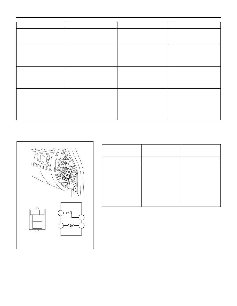
POWER RELAY CHECK
M1552008800321
BLOWER RELAY CONTINUITY CHECK
Hissing or swishing
noise
Low refrigerant quantity
Refrigerant level
Check system for leaks
and charge to
specification
Rattling (Internal
compressor)
Lack of lubricating oil. In a
system with a gas leak
the oil has escaped with
the refrigerant
Rattling noise from
internal compressor
Repalce the compressor
and also fix the system
leak to prevent
reoccurrance
Wooing (Resonant
noise)
Drive accessory (P/S
pump, Alternator,etc)
resonating at specific
engine speed
The drive accessories for
vibration
Stop vibrations of the
assembly or modify
transmission route to the
vehicle body
Cooing (Discharge
pulsation noise)
Pressure fluctuation of
refrigerant discharged
from compressor, which
vibrates the high pressure
piping
Remove the piping
mounting clamps and
re-check. Hold the
condenser without
mountings by hand and
re-check
Put rubber bush between
pipe clamps and the
vehicle body. decrease
refrigerant to minimum
specified level.
NOISE DESCRIPTION
POSSIBLE CAUSE
CHECK
REPAIR
BATTERY
VOLTAGE
TESTER
CONNECTION
SPECIFIED
CONDITION
Not applied
4
− 5
Open circuit
• Connect
terminal 1 to the
positive battery
terminal
• Connect
terminal 3 to the
negative battery
terminal
4
− 5
Less than 2 ohms
25DB057A
4
5
1 2 3
5
1
4
3
BLOWER RELAY