Mitsubishi 380. Manual - part 133
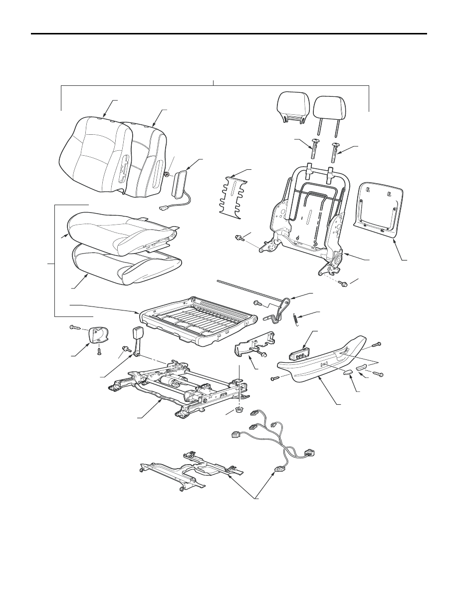
FRONT SEAT ASSEMBLY
INTERIOR
52A-40
LHS: 380GT (leather)
19DB014A
17
18
15
15
13
22
21
20
3
5
4
6
7
23
24
2
1
10
11
12
14
8
9
35 N·m
35 N·m
45 N·m
5 N·m
19
32 N·m
|
|
|
FRONT SEAT ASSEMBLY INTERIOR 52A-40 LHS: 380GT (leather) 19DB014A 17 18 15 15 13 22 21 20 3 5 4 6 7 23 24 2 1 10 11 12 14 8 9 35 N·m 35 N·m 45 N·m 5 N·m 19 32 N·m |