Mitsubishi 380. Manual - part 76
SYMPTOM PROCEDURES
SIMPLIFIED WIRING SYSTEM (SWS)
54B-301
STEP 25. Check the wiring harness between headlamp
(RH) connector A-32 (terminals 5 and 1) and ground.
Q: Is the wiring harness between headlamp (RH) connector
A-32 (terminals 5 and 1) and ground in good condition?
YES : No action is necessary and testing is complete.
NO : The wiring harness may be damaged or the
connector(s) may have loose, corroded or damaged
terminals, or terminals pushed back in the connector.
Repair the wiring harness as necessary. Verify that
the headlamps illuminate normally.
INSPECTION PROCEDURE H-8: Headlamp and Taillamp: The High-beam indicator lamp does not
illuminate.
NOTE: This troubleshooting procedure requires the
use of Diagnostic Tool MB991958 and SWS monitor
kit MB991813. For details on how to use the SWS
monitor, refer to "How to connect SWS monitor
."
.
CIRCUIT OPERATION
At the same time that the high beams are illumi-
nated, the ETACS-ECU sends a signal to illuminate
the high beam indicator via the CAN bus line.
.
TECHNICAL DESCRIPTION (COMMENT)
If the high beam indicator does not illuminate nor-
mally, connector(s), wiring harness in the CAN bus
lines, the ETACS-ECU or the combination meter may
be defective.
.
TROUBLESHOOTING HINTS
• Refer to circuit diagrams GROUP-
• Refer to configuration diagrams GROUP-
• The wiring harness or connectors may have
loose, corroded, or damaged terminals, or termi-
nals pushed back in the connector
• The combination meter may be defective
• The ETACS-ECU may be defective
.
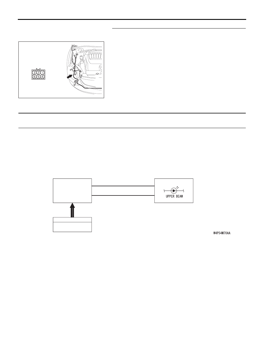
16DB433A
A-32
CONNECTORS: A-32
INPUT SIGNAL
ETACS-
ECU
DIMMER SWITCH
COMBINATION
METER
CAN COMMUNICATION LINE
(CAN_L LINE)
CAN COMMUNICATION LINE
(CAN_H LINE)
High-Beam Indicator Light Circuit