Mercedes-Benz Sprinter / Dodge Sprinter. Manual - part 489
HOOD
TABLE OF CONTENTS
page
page
HINGE
. . . . . . . . . . . . . . . . . . . . . . . . . . . . . 51
. . . . . . . . . . . . . . . . . . . . . . . . . 51
HOOD
. . . . . . . . . . . . . . . . . . . . . . . . . . . . . 51
. . . . . . . . . . . . . . . . . . . . . . . . . 51
. . . . . . . . . . . . . . . . . . . . . . . . 52
LATCH
. . . . . . . . . . . . . . . . . . . . . . . . . . . . . 52
. . . . . . . . . . . . . . . . . . . . . . . . . 52
LATCH RELEASE CABLE
. . . . . . . . . . . . . . . . . . . . . . . . . . . . . 52
. . . . . . . . . . . . . . . . . . . . . . . . . 52
LATCH RELEASE HANDLE
. . . . . . . . . . . . . . . . . . . . . . . . . . . . . 52
. . . . . . . . . . . . . . . . . . . . . . . . . 52
PROP ROD
. . . . . . . . . . . . . . . . . . . . . . . . . . . . . 53
. . . . . . . . . . . . . . . . . . . . . . . . . 53
SAFETY LATCH
. . . . . . . . . . . . . . . . . . . . . . . . . . . . . 53
. . . . . . . . . . . . . . . . . . . . . . . . . 54
HINGE
REMOVAL
NOTE: It is not necessary to remove the hood to
replace one or both hinges. The hinges can be
replaced one at a time.
(1) Open hood and support as needed.
(2) Using a grease pencil or equivalent, mark the
position of the hinge on the hood and cowl.
(3) Remove the two hood nuts.
(4) Remove the two cowl bolts and remove hinge.
INSTALLATION
(1) Position hinge on vehicle and align reference
marks.
(2) Install cowl bolts and tighten to 23 N·m (17 ft.
lbs.).
(3) Install hood nuts and tighten to 23 N·m (17 ft.
lbs.).
(4) Check and adjust hood if necessary. (Refer to
23 - BODY/HOOD/HOOD - ADJUSTMENTS)
HOOD
REMOVAL
(1) Raise and support hood.
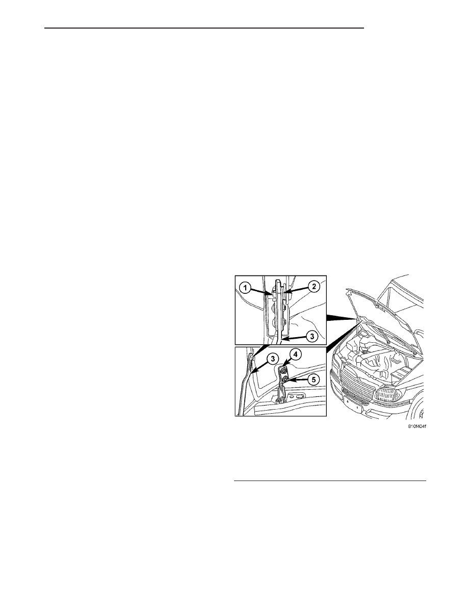
(2) Remove the prop rod retaining clip. (Fig. 1)
(3) Separate the prop and spring from the hood.
(4) Using a grease pencil or equivalent, mark loca-
tion of hood hinges on hood for installation align-
ment.
(5) Remove nuts attaching hinges to hood.
(6) With the aid of a helper, remove hood from
vehicle.
INSTALLATION
(1) Position hood on hinges.
(2) Install nuts finger-tight.
(3) Connect spring and prop onto hood and install
the retaining spring.
(4) Align hinges with installation reference marks
and tighten bolts to 23 N·m (17 ft. lbs.).
(5) Check and adjust as necessary. (Refer to 23 -
BODY/HOOD/HOOD - ADJUSTMENTS)
Fig. 1 HOOD
1 - PROP ROD RETAINING CLIP
2 - PROP SPRING
3 - PROP ROD
4 - HINGE
5 - NUTS (2)
VA
HOOD
23 - 51