Mercedes-Benz Sprinter / Dodge Sprinter. Manual - part 484


  Index      Mercedes     Mercedes-Benz Sprinter / Dodge Sprinter - service repair manual 2006 year


Search            


Content   ..  482  483  484  485   ..


Mercedes-Benz Sprinter / Dodge Sprinter. Manual - part 484


NOTE: Remove any mineral spirits with a clean
cloth after glass installation.

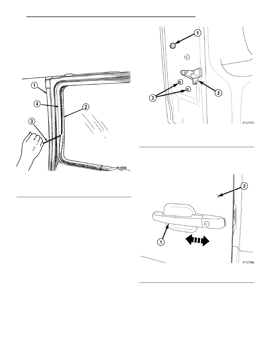
(6) Verify that the seal is seated in the window

opening (Fig. 12).

(7) Test the window for water leaks. (Refer to 23 -

BODY - DIAGNOSIS AND TESTING - WATER
LEAKS)

EXTERIOR HANDLE

REMOVAL

(1) Remove handle bolt. (Fig. 13)

NOTE: Front door shown, rear door similar.

(2) Slide handle assembly towards front of door.

(Fig. 14)

NOTE: Front door shown, rear door similar.

(3) Pull rear of handle out away from door and dis-

engage the latch levers.

(4) Slide handle towards the rear of door and

remove.

INSTALLATION

(1) Position front of handle into front slot in door.

(Fig. 15)

NOTE: Front door shown, rear door similar.

Fig. 12 Glass & Weatherstrip Seal Installation

1 - BODY PANEL
2 - WEATHERSTRIP SEAL
3 - INSTALLATION CORD
4 - WINDOW OPENING

Fig. 13 EXTERIOR HANDLE

1 - EXTERIOR HANDLE BOLT
2 - LATCH
3 - LATCH BOLTS (3)

Fig. 14 LATCH/HANDLE FASTENERS

1 - EXTERIOR HANDLE
2 - DOOR

VA

DOORS - REAR

23 - 31

(2) Position rear of handle into latch opening and

engage lock and latch actuation levers with the latch
levers. (Fig. 16)

NOTE: Front door shown, rear door similar.

(3) Slide exterior handle towards rear of door and

install bolt. (Fig. 17)

NOTE: Front door shown, rear door similar.

(4) Tighten bolt to 10 N·m (89 in. lbs.).

HINGE

REMOVAL

NOTE: It is not necessary to remove the door to
replace the hinges if they are replaced one at a
time.

(1) Using a grease pencil or equivalent, mark the

position of the hinge on the door.

(2) Remove the bolts and remove the hinge. (Fig.

18)

Fig. 15 EXTERIOR HANDLE INSTALLATION

1 - DOOR LATCH OPENING
2 - LOCK ACTUATION LEVER
3 - LATCH ACTUATION LEVER
4 - EXTERIOR HANDLE

Fig. 16 LATCH LEVERS

1 - LATCH LEVER
2 - LATCH OPENING
3 - LOCK LEVER

Fig. 17 EXTERIOR HANDLE

1 - EXTERIOR HANDLE BOLT
2 - LATCH
3 - LATCH BOLTS (3)

23 - 32

DOORS - REAR

VA

INSTALLATION

(1) Install hinge and install bolts.
(2) Tighten bolts to 25 N·m (18 ft. lbs.).
(3) Adjust door if necessary. (Refer to 23 - BODY/

DOOR - FRONT/DOOR - ADJUSTMENTS)

INSIDE HANDLE ACTUATOR

REMOVAL

(1) Remove the handle trim cover. (Fig. 19)
(2) Remove the screws and handle.
(3) Disconnect the latch cable.

INSTALLATION

(1) Connect the latch cable.
(2) Install handle and screws.
(3) Install trim cover.

LATCH

REMOVAL

(1) Disconnect and isolate battery negative cable.
(2) Remove right side trim panel. (Refer to 23 -

BODY/DOORS - REAR/TRIM PANEL - REMOVAL)

(3) Disconnect lock rod. (Fig. 20)
(4) Remove the screws and pull out latch from

door.

(5) Disconnect cable and electrical connectors.

Fig. 18 REAR DOOR HINGE

1 - TORX BOLTS BODY SIDE
2 - TORX BOLTS DOOR SIDE
3 - HINGE
4 - ALLEN BOLT

Fig. 19 TRIM PANEL

1 - TRIM
2 - INSIDE HANDLE ACTUATOR
3 - TRIM PANEL
4 - CONTROL CABLE

VA

DOORS - REAR

23 - 33

INSTALLATION

(1) Connect electrical connectors and cable to latch

assembly.

(2) Install latch in door and install screws.
(3) Connect lock rod.
(4) Install right side trim panel. (Refer to 23 -

BODY/DOORS - REAR/TRIM PANEL - INSTALLA-
TION)

(5) Connect battery negative cable.

TRIM PANEL

REMOVAL

(1) Remove trim and interior handle, if equipped

(Fig. 21). (Refer to 23 - BODY/DOORS - REAR/IN-
SIDE HANDLE ACTUATOR - REMOVAL)

(2) Remove push pin fasteners, if equipped.
(3) Using a trim stick C-4755 or equivalent,

remove the lower trim panel.

(4) Remove rivets and remove upper trim panel, if

equipped.

INSTALLATION

(1) Install upper trim panel and replace rivets.
(2) Install lower trim and install push pin fasten-

ers, if equipped.

(3) Install interior handle, if equipped. (Refer to 23

- BODY/DOORS - REAR/INSIDE HANDLE ACTUA-
TOR - INSTALLATION)

Fig. 20 LATCH

1 - DOOR LOCK KNOB
2 - ELECTRIC
3 - CABLE
4 - LOCK ROD
5 - LATCH ASSEMBLY
6 - ELECTRICAL CONNECTORS ROUTING
7 - SCREWS (3)

Fig. 21 TRIM PANEL

1 - TRIM
2 - INSIDE HANDLE ACTUATOR
3 - TRIM PANEL
4 - CONTROL CABLE

23 - 34

DOORS - REAR

VA


Content   ..  482  483  484  485   ..