Mercedes-Benz Sprinter / Dodge Sprinter. Manual - part 483
ASSEMBLY
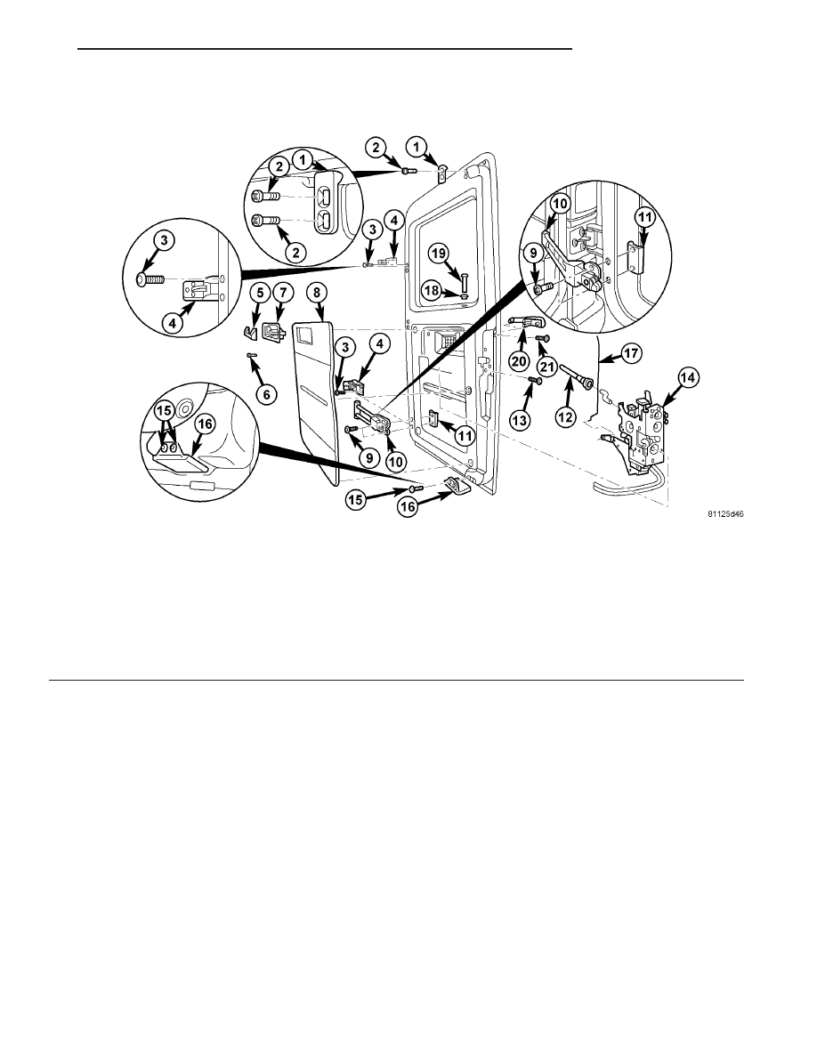
RIGHT DOOR
(1) Install the door hinges (4) and bolts (3) (Fig. 6).
(Refer to 23 - BODY/DOORS - REAR/HINGE -
INSTALLATION)
(2) Install the door check (10) and bolts (9). (Refer
to 23 - BODY/DOORS - REAR/CHECK - INSTALLA-
TION)
(3) Install the top closing wedge (1) and bolts (2).
(4) Install the bottom closing wedge (16) and
replace rivets (15).
(5) Install the exterior handle (20). (Refer to 23 -
BODY/DOORS
-
REAR/EXTERIOR
HANDLE
-
INSTALLATION)
(6) Install the latch assembly (14). (Refer to 23 -
BODY/DOORS - REAR/LATCH - INSTALLATION)
(7) Install trim panel (20). (Refer to 23 - BODY/
DOORS - REAR/TRIM PANEL - INSTALLATION)
(8) Install door. (Refer to 23 - BODY/DOORS -
REAR/DOOR - INSTALLATION)
Fig. 6 RIGHT DOOR
1 - TOP CLOSING WEDGE
12 - DOOR LOCK LINKAGE
2 - BOLTS
13 - BOLTS (3)
3 - BOLTS (2)
14 - LATCH ASSEMBLY
4 - DOOR HINGE
15 - RIVETS (2)
5 - PANEL
16 - BOTTOM CLOSING WEDGE
6 - SCREW
17 - LOCKING ROD
7 - INNER ACTION
18 - GROMMET
8 - PANELING
19 - LOCKING KNOB
9 - BOLTS (2)
20 - EXTERIOR DOOR HANDLE
10 - DOOR CHECK
21 - SCREW
11 - THREADED PLATE
VA
DOORS - REAR
23 - 27